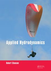
 Author's
website : http://www.uq.edu.au/~e2hchans/
(1) Flow past a Rankine body, where the green dye injected at the source does not mix with the red dye injected in the uniform flow (flow from left to rigth).
(2) Flow past a thick rounded plate perpendicular to the flow (flow from right to left).
(3) Flow past a thick rounded foil with 15% camber perpendicular to the flow (flow from right to left)
2015 Project on Wind Loads on Buildings
Read the Instructions. (Version 1.09. 9/04/2015)
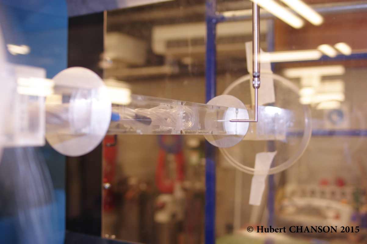
Photo No. 2015.1: Hot-wire probe measurements
Photo No. 2015.2: Probe traverse mechanism
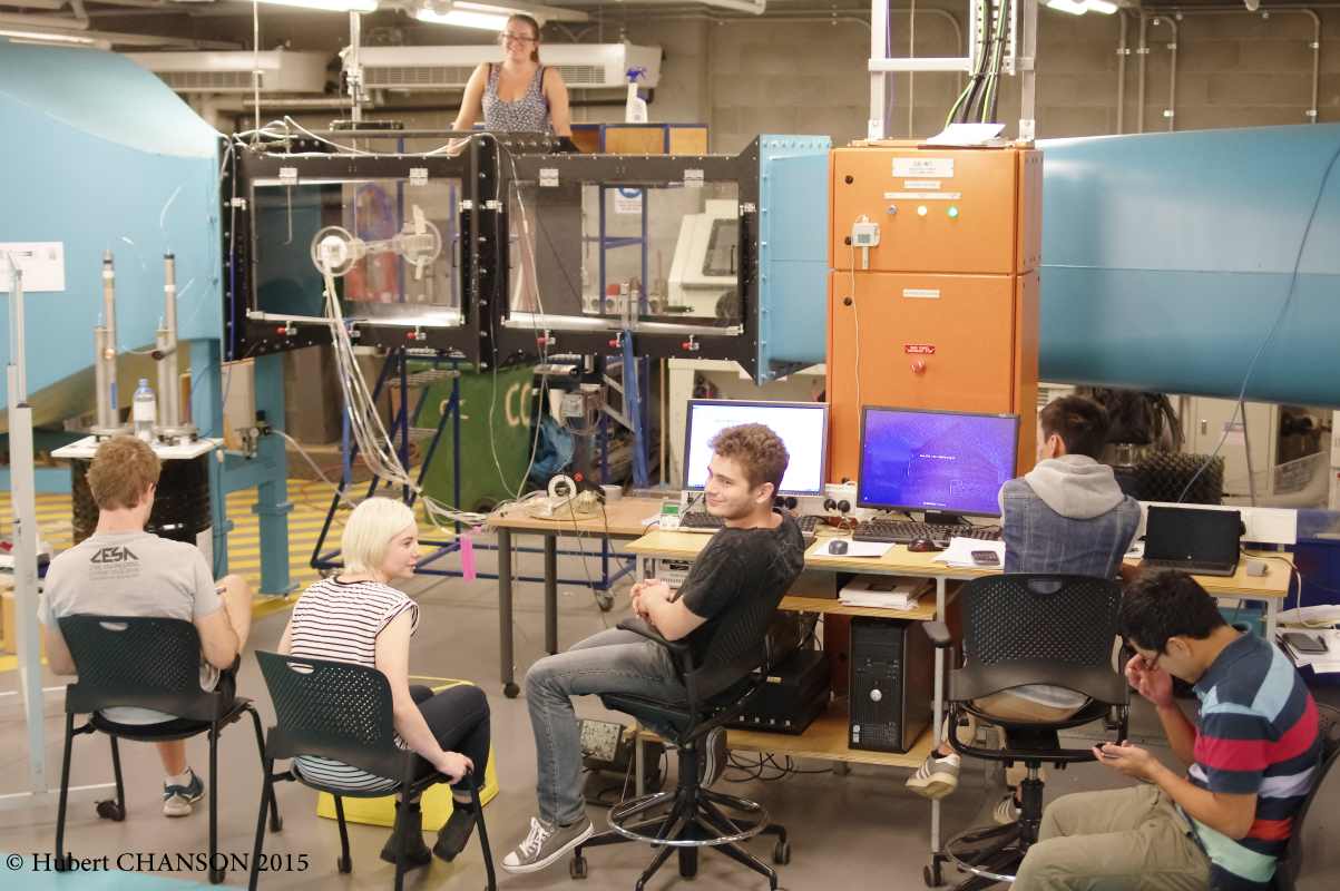
Photo No. 2015.3: Computer data acquisition and probe signal sampling.
Photo No. 2015.4: Wind tunnel test section and students conducting velocity measurements around the building model
Photo No. 2015.5: Students conducting probe sampling and data analysis
Photo No. 2015.6: Hot-wire probe in the near wake of the building model for 0-degree angle of incidence
2008 Project on Cyclonic Wind Loads on Buildings at the University of Queensland
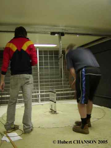
Photo No. 1.1 : Group 1 students preparing the building model M2 in the wind tunnel, looking donwstream at the turn table
Photo No. 1.2 : Control room of the wind tunnel, view from the test section (Group 1)
Photo No. 2.1 : Control room of the wind tunnel, view from the test section (Group 2)
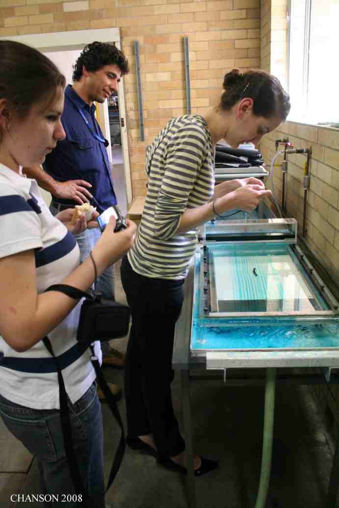
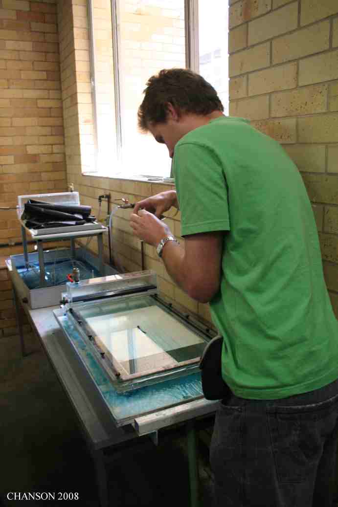
Photo No. 2.2 : Hele-Shaw cell experiment (Group 2) (Courtesy of Paul GUARD)
Photo No. 4.1 : Preparation of the rough plate boundary layer experiment (Group 4)
Photo No. 4.2 : Preparation of the building model M3 (Group 4) (Courtesy of Paul GUARD)
Photo No. 3.1 : Hele-Shaw cell experiment (Group 3) (Courtesy of Paul GUARD)
Photo No. 3.2 : Streamline visualisation in the Hele-Shaw cell apparatus (Group 3) (Courtesy of Paul GUARD)
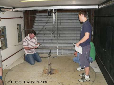
2006 Atmospheric Boundary Layer Wind Tunnel Project (Cyclonic Wind Loads on Buildings)
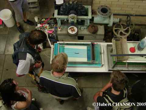
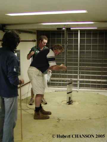
2005 Wind tunnel projects
Rating : [***] = superb, must see - [**] = excellent* Flow visualisation
|
|
|
Deposits at UQeSpace |
Back to Prof Hubert CHANSON's Home Page