Gold Creek Dam and its Historical Stepped Spillway System
by Hubert CHANSON (h.chanson@uq.edu.au)
M.E., ENSHM Grenoble, INSTN, PhD (Cant.), DEng (Qld),
Eur.Ing., MIEAust., MIAHR, 13th
Arthur Ippen awardee
Dept. of Civil Engrg., Univ. of Queensland, Brisbane QLD
4072, Australia
 Presentation
The Gold Creek dam was designed by John HENDERSON (1836-1916) for the
Brisbane Board of Waterworks (WHITMORE 1996, COSSINS 2000). The purpose of the dam was to
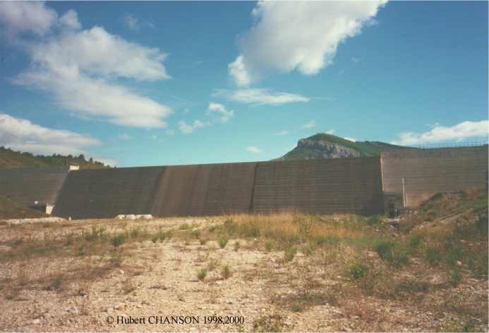
increase the water supply for the city of Brisbane. The dam built between
1882 and 1885 is an earthfill embankment with a clay puddle corewall . It
was built under the general supervision of HENDERSON and the site engineer
was Alexander STEWART (1843-1900). The length of the dam is 187-m
(624 ft) and the maximum height of the embankment is 26-m (86 ft). The
reservoir storage capacity is about 1.8 10+6 m3. The catchment area is
10.48 km2 of protected forest area.
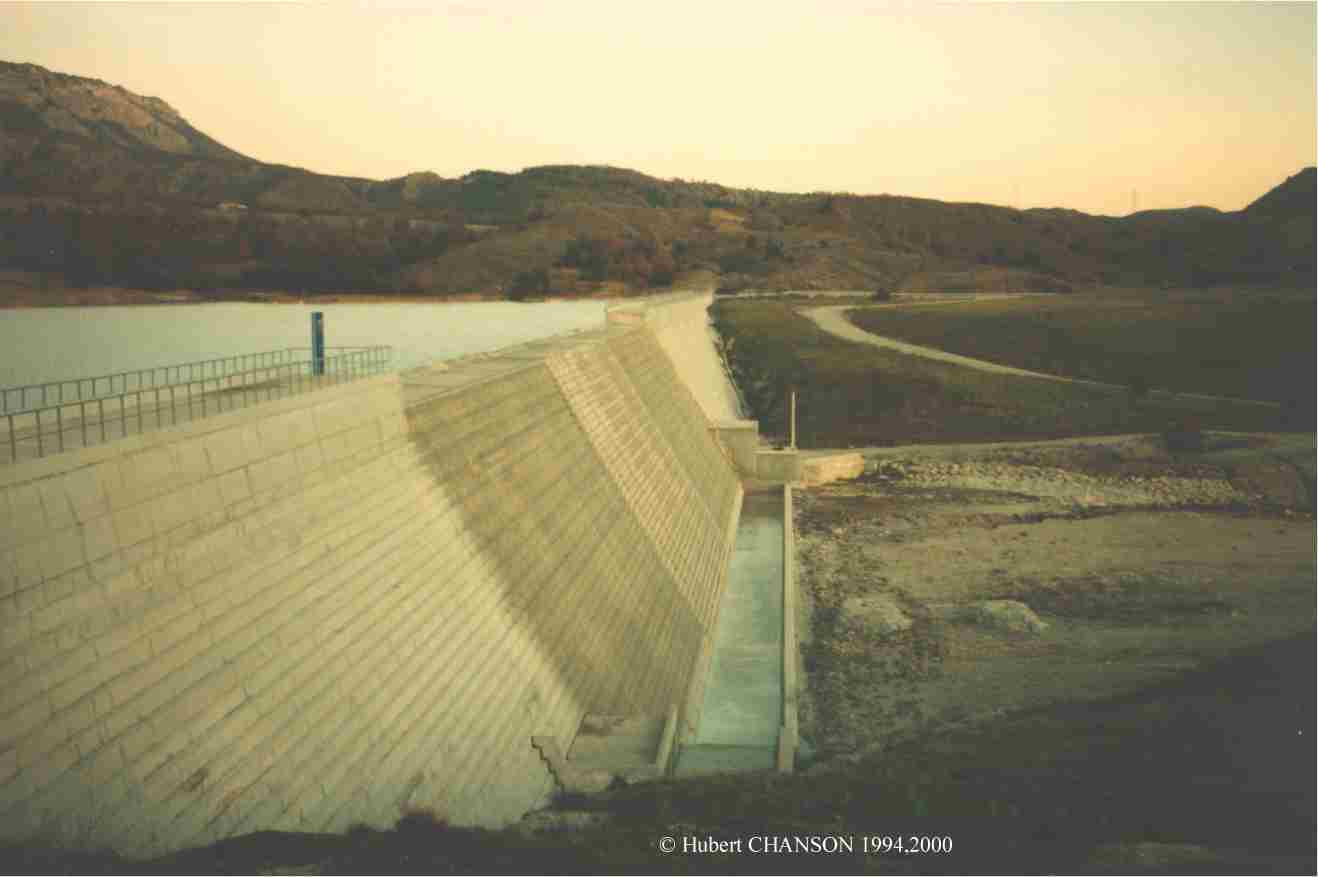
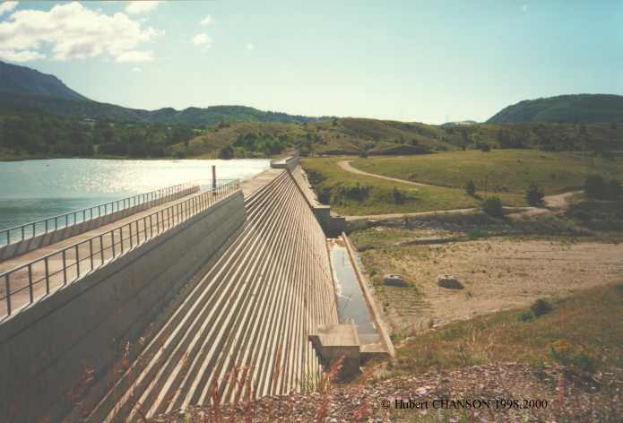
An overflow spillway is located on the left abutment on rock foundation.
An outlet tower was built between 1883 and 1885 to draw water from the
reservoir. The original structure in cast iron failed in 1904, following
improper operation while the reservoir was empty. The structure was
replaced by the present concrete structure built in 1905.
Originally, the Gold Creek reservoir supplied water directly to the city.
In 1928, the reservoir was connected to Enoggera reservoir via a tunnel
beneath the ridge separating Enoggera Creek and Gold Creek basins. The
Gold Creek dam acted as an upper reservoir for the Enoggera reservoir as
the Gold Creek reservoir is located close to and at a higher elevation
than the Enoggera dam. Nowadays the Gold Creek reservoir is no longer in
use, the pipeline having been decommissioned in 1991. The reservoir is
managed by Brisbane
Forest Park, and it was
kept nearly full until early 2004 when the water level was artifically
lowered for dam safety.
The spillway system
The Gold Creek catchment area and the neighboring Enoggera Creek basin can
be subjected to very intense rainfalls : e.g., 920 mm during a storm on 24
January 1974. Since dam construction, the spillway has been modified four
times essentially, each time to increase the discharge capacity (CHANSON
and
WHITMORE 1998).
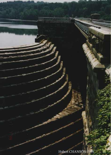
 The original 1885 spillway was
a crude channel cut in the left abutment. In 1887, the spillway channel
was widened by 15 m. In January 1887 and March 1890, large overflows
occurred and the unlined rock spillway was badly damaged (CHANSON
and WHITMORE 1996). As a result it was decided to build a masonry
spillway in 1890. The design was approved by J. HENDERSON and the
drawing of the spillway was signed by A. STEWART. It is believed that the
contractors for the spillway were COWLEY and ANNEAR. The 1890 spillway was
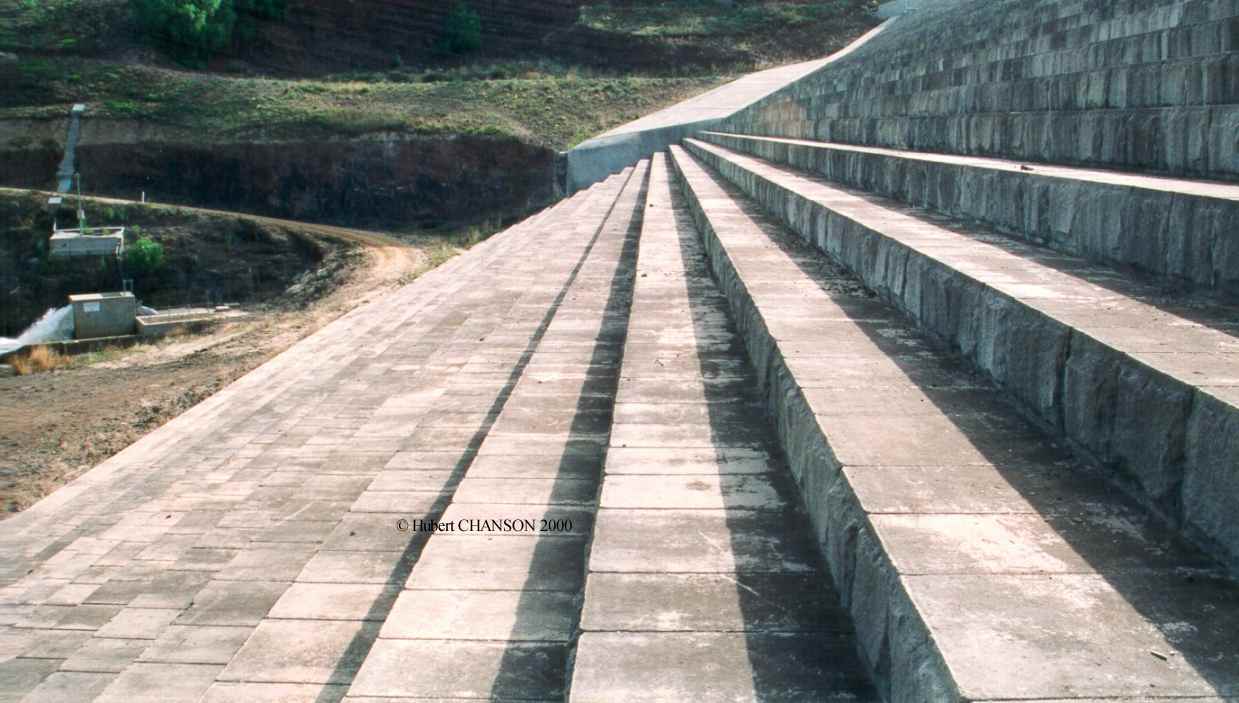
a staircase structure made of concrete, the concrete aggregate being
obtained from the original spillway rock material . The final staircase
structure had twelve steps (1.5 m high) although some original drawings
showed originally 19 steps. In 1920, a low concrete wall was built across
the spillway crest to increase the reservoir capacity. It was dismantled
in 1932 (WHITMORE 1996). In 1975, the level of
the spillway crest was lowered by 1.2-m (4 feet) to increase the maximum
discharge capacity but the steep channel was unmodified. In 1998,
the spillway crest was lowered by another 0.3 m. Today's spillway consists
of the 1998 crest followed by the 1890 stepped channel, although a 5 m cut in the middle of the spillway crest
was made in 2004 to lower the water rervoir.
The original 1885 spillway was
a crude channel cut in the left abutment. In 1887, the spillway channel
was widened by 15 m. In January 1887 and March 1890, large overflows
occurred and the unlined rock spillway was badly damaged (CHANSON
and WHITMORE 1996). As a result it was decided to build a masonry
spillway in 1890. The design was approved by J. HENDERSON and the
drawing of the spillway was signed by A. STEWART. It is believed that the
contractors for the spillway were COWLEY and ANNEAR. The 1890 spillway was
a staircase structure made of concrete, the concrete aggregate being
obtained from the original spillway rock material . The final staircase
structure had twelve steps (1.5 m high) although some original drawings
showed originally 19 steps. In 1920, a low concrete wall was built across
the spillway crest to increase the reservoir capacity. It was dismantled
in 1932 (WHITMORE 1996). In 1975, the level of
the spillway crest was lowered by 1.2-m (4 feet) to increase the maximum
discharge capacity but the steep channel was unmodified. In 1998,
the spillway crest was lowered by another 0.3 m. Today's spillway consists
of the 1998 crest followed by the 1890 stepped channel, although a 5 m cut in the middle of the spillway crest
was made in 2004 to lower the water rervoir.
The maximum discharge capacity of the 1890 spillway was probably selected
to pass the maximum observed flood at the time : i.e., 170 m3/s in January
1887. The "theoretical" discharge capacity of the 1975 and 1998 spillways
is much larger (360 m3/s for 1975 crest design, ~600 m3/s for 1998 crest
design). But CHANSON and WHITMORE (1996,1998)
showed that the maximum capacity of the stepped channel is 280 m3/s. For
larger discharges, overtopping of the right sidewall would occur, causing
unacceptable scouring and erosion at the embankment dam toe.
Discussion
Since Antiquity, dam engineers learned the risks of dam erosion and
destruction associated with large floods, and it was usual to design dams
with a spillway system. In most early dams, the waters were discharged
over the dam crest or beside the dam. In ancient structures, a stepped
spillway design was selected to contribute to the stability of the dam and
simplicity of shape (CHANSON 2001). Later design
engineers realised the advantages of stepped channels for energy
dissipation purposes and to prevent scouring.
During the 19th century, overflow stepped spillways were selected
frequently, with nearly one third of the dams built in USA being equipped
with a stepped cascade. Most structures were masonry and concrete dams
with a downstream stepped face reinforced by granite blocks (e.g. Goulburn
weir). Some dams were equipped with stepped rocklined spillways :
e.g., Ternay and La Tâche dams.
Others had a lateral spillway (e.g. Le
Pont dam). Earth embankments were usually equipped a lateral
spillway (e.g. Val House dam, Gold Creek dam). The development of stepped
spillway was marked by two milestones : the Gold Creek dam cascade (1890,
Australia) and the New Croton dam
(1906, USA). It is believed that the Gold Creek cascade was the world's
first concrete stepped spillway and the ancestor of modern
RCC stepped spillways (CHANSON and WHITMORE 1998). Completed in
1906, the New Croton dam spillway is probably the first stepped chute
designed specifically to maximise energy dissipation. It is still in use
despite a major accident in 1955 (CHANSON 2001).
The educational role of Gold
Creek dam and spillway
 Water supply in Australia is
limited because of the dry climate. Hydraulic engineering expertise is
therefore critical to the country's future developments, and most
undergraduate civil and environmental engineering curricula in Australian
universities include a significant hydraulics component. At the University
of Queensland, hydraulics and water resource engineering are lectured in
the civil and environmental engineering curricula. The lecture material is
structured to guide the students from the basic principles of fluid
mechanics to their application to engineering design (CHANSON
2001b). The focus is on the basic understanding of fundamental
principles and their sound applications to real-world applications. In the
context of undergraduate and postgraduate subjects, design applications in
classroom are restricted to simple flow situations and boundary conditions
for which the basic equations can be solved analytically or with simple
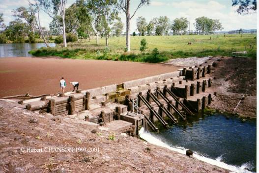
models. Field work activities (Photo No. 3)
are essential to illustrate real professional situations, and the complex
interactions between all engineering and non-engineering constraints (e.g.
CHANSON 2001,2004). For example, the
construction of a dam and reservoir across a river involves first a study
of the stream hydrology and catchment characteristics, while the design of
the weir is based upon structural, geotechnical and hydraulic
considerations. A consequent cost of the structure is off course the
spillway, designed to pass safely the maximum peak flood. In addition the
impact of the weir on the upstream and downstream valleys must be
considered.
Water supply in Australia is
limited because of the dry climate. Hydraulic engineering expertise is
therefore critical to the country's future developments, and most
undergraduate civil and environmental engineering curricula in Australian
universities include a significant hydraulics component. At the University
of Queensland, hydraulics and water resource engineering are lectured in
the civil and environmental engineering curricula. The lecture material is
structured to guide the students from the basic principles of fluid
mechanics to their application to engineering design (CHANSON
2001b). The focus is on the basic understanding of fundamental
principles and their sound applications to real-world applications. In the
context of undergraduate and postgraduate subjects, design applications in
classroom are restricted to simple flow situations and boundary conditions
for which the basic equations can be solved analytically or with simple
models. Field work activities (Photo No. 3)
are essential to illustrate real professional situations, and the complex
interactions between all engineering and non-engineering constraints (e.g.
CHANSON 2001,2004). For example, the
construction of a dam and reservoir across a river involves first a study
of the stream hydrology and catchment characteristics, while the design of
the weir is based upon structural, geotechnical and hydraulic
considerations. A consequent cost of the structure is off course the
spillway, designed to pass safely the maximum peak flood. In addition the
impact of the weir on the upstream and downstream valleys must be
considered.
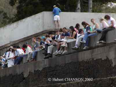
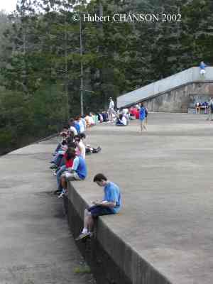
 Although first introduced to
motivate students' interest, field studies in undergraduate hydraulic
courses have been an integral part of the teaching pedagogy for more than
ten years at the University of Queensland (CHANSON
2004). Gold Creek dam is one of the best field study sites for
University students based in Brisbane . Photo
No. 4 and Photo N. 5A show
respectively E2408 Hydraulic design students and CIVL3140 Open channel
flow students inspecting the Gold Creek dam and its spillway system under
the expert guidance of the writer. Key features of the main spillway
include a 55-m wide 60-m long broad crest, a stepped chute completed in
1890 and the absence of downstream stilling basin. During the field work,
students surveyed the broad-crest, inspected the steep stepped chute and
investigated the downstream energy dissipator (Photo
No. 5B).
Although first introduced to
motivate students' interest, field studies in undergraduate hydraulic
courses have been an integral part of the teaching pedagogy for more than
ten years at the University of Queensland (CHANSON
2004). Gold Creek dam is one of the best field study sites for
University students based in Brisbane . Photo
No. 4 and Photo N. 5A show
respectively E2408 Hydraulic design students and CIVL3140 Open channel
flow students inspecting the Gold Creek dam and its spillway system under
the expert guidance of the writer. Key features of the main spillway
include a 55-m wide 60-m long broad crest, a stepped chute completed in
1890 and the absence of downstream stilling basin. During the field work,
students surveyed the broad-crest, inspected the steep stepped chute and
investigated the downstream energy dissipator (Photo
No. 5B).
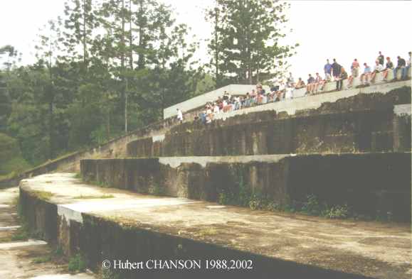
Students can become thrilled by relevant field studies directly relevant
to the course material and Gold Creek dam field studies are no exception.
For example, a broad-crested weir is often perceived as a "dull" structure
in the classroom, but it may become a
fascinating hydraulic structure in the context of a hydraulics field work,
particularly with large structures (Photo
No. 5B). The students gain also first hand experience on real-world
issues associated with a hydraulic structure design. At Gold Creek dam,
these include road access (incl. road submergence during floods), earth
embankment dam design, concrete durability (1890 concrete steps) and
spillway refurbishments.
Note that the pedagogical role of the Gold Creek dam and spillway have
been acknowledged in publications by the American Society for Civil
Engineers (Journal of Hydraulic
Engineering, Dec 2001 & Journal
of Professional Issues in Engineering Education and Practice,
Oct. 2004), while photographs of Gold Creek dam student field trips were
published in a number of textbooks (e.g. Elsevier-Butterworh-Heinemann
2004, Balkema 2001).
Summary
In summary, a University of Queensland team lead by Hubert
CHANSON has investigated the historical development of the Gold
Creek dam stepped cascade and its hydraulic characteristics. The
University study suggests a sound design of the dam and the cascade, a
1890 cascade design based on Australian and overseas experience (Victoria,
Great Britain, France).
Unique features of the stepped spillway include the only stepped cascade
built in Queensland before 1900, and the world's
first use of non reinforced concrete as construction material for a
stepped spillway. The stepped spillway is a superb example of
Engineering Heritage considering its safe operation for more than a
century and the sound cascade design by today's standards. It is the
strong belief of the writer that the Gold Creek dam stepped spillway
should be heritage listed, and that its international significance be
recognised by local, state and federal governments in Australia.
Further the Gold Creek dam and its spillway system are unique educational
and pedagogical facilties to further the education and expertise of future
graduates and professionals.
Detailed
photographs
 Gold
Creek
dam
Gold
Creek
dam
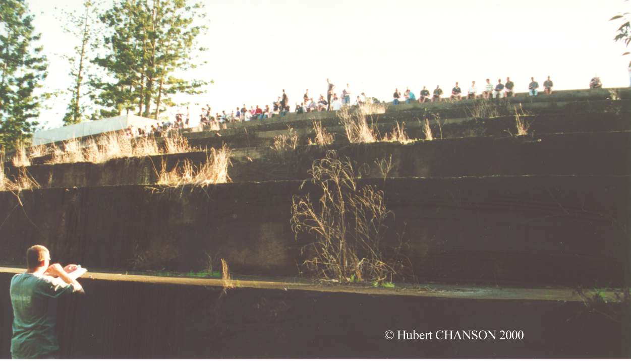
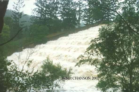
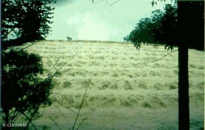
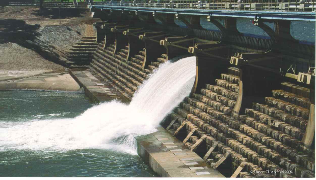
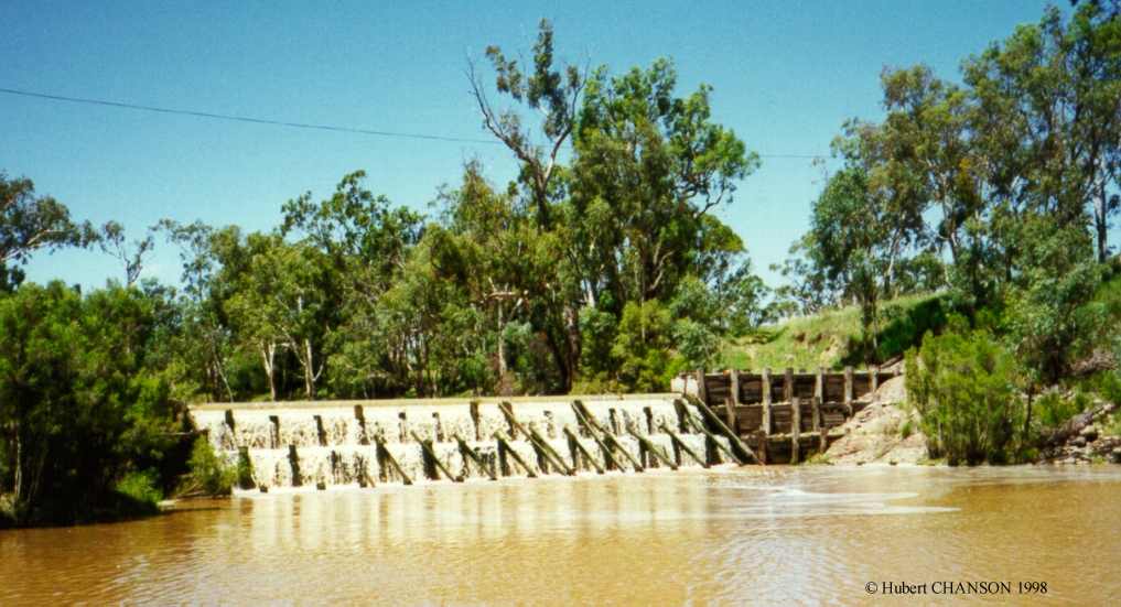
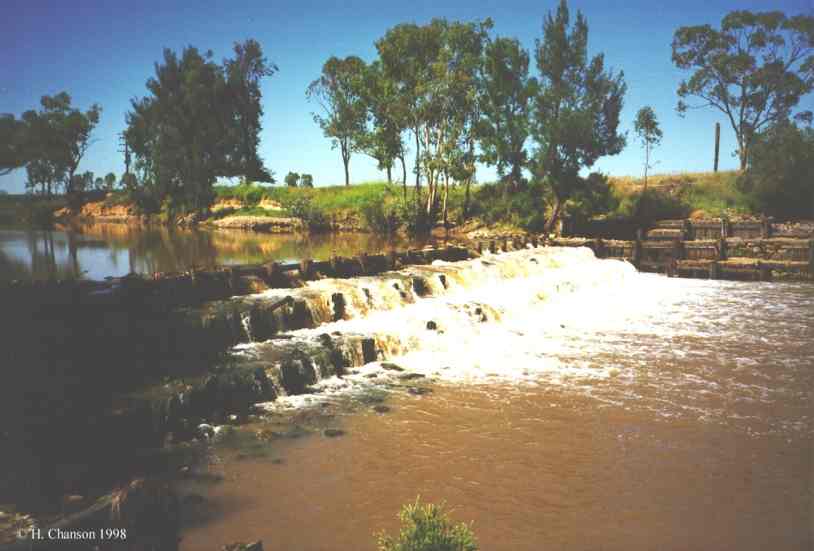
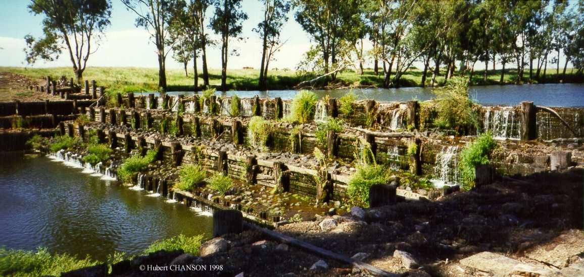
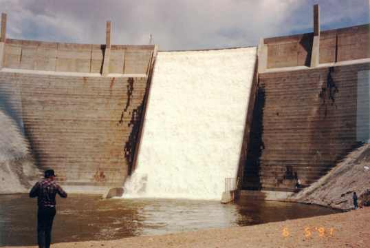
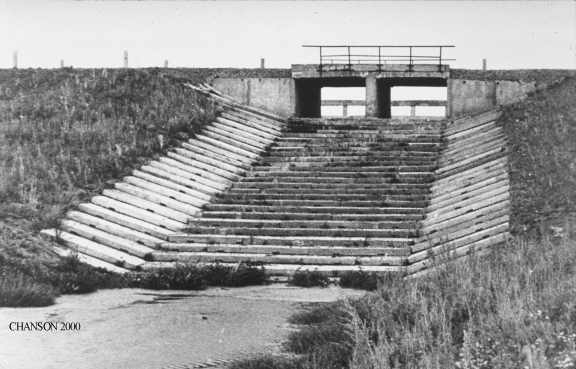
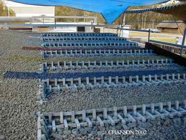
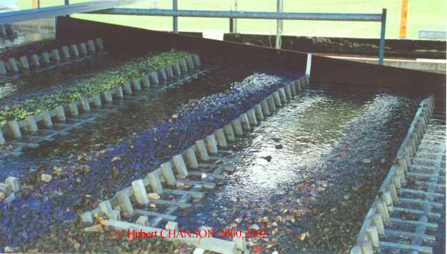
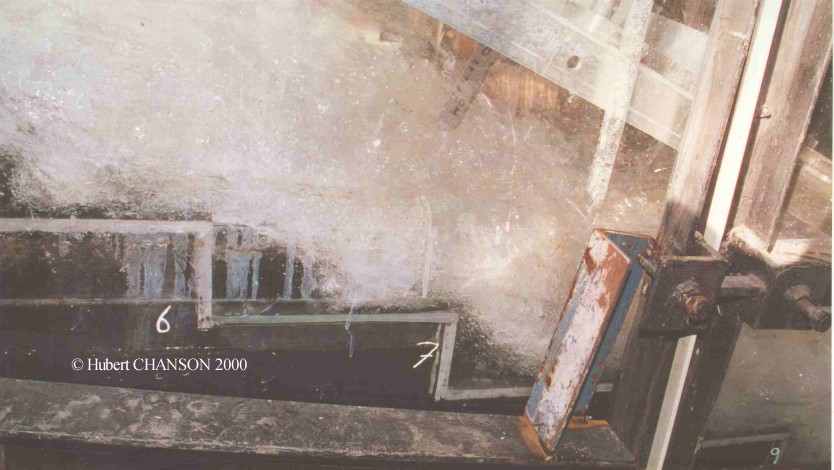
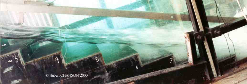
Photo No. 1 : Gold Creek dam stepped spillway in operation in May
1996 : View from downstream, view from left bank, view
from right bank bottom.
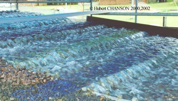
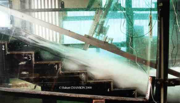
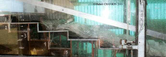
Photo No. 2 : Overflow in May 1996 - View
from left bank. Front cover of the Canadian Journal of Civil Engineering
1998, No. 4.
Photo No. 3 : Field trip with students
on 9 Sept. 1998.
Photo No. 4 : Field trip with students
in Aug. 2000.
Photo No. 5 : Student field trip on 11 Sept. 2002 : Photo
5a and Photo 5b
Photo No. 6 : Gold Creek reservoir on
25 Sept. 2006; note the low water reservoir level.
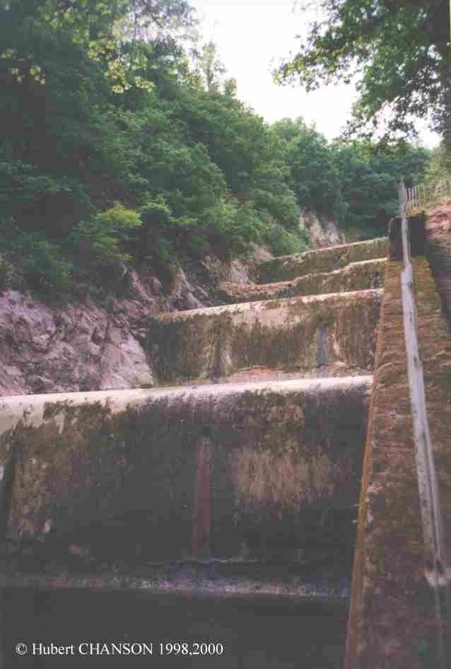
Photo No. 7 : Intake tower on 22 Sept.
2006; the intake tower was built in 1905, to replace the original cast-iron
tower which failed in 1904.
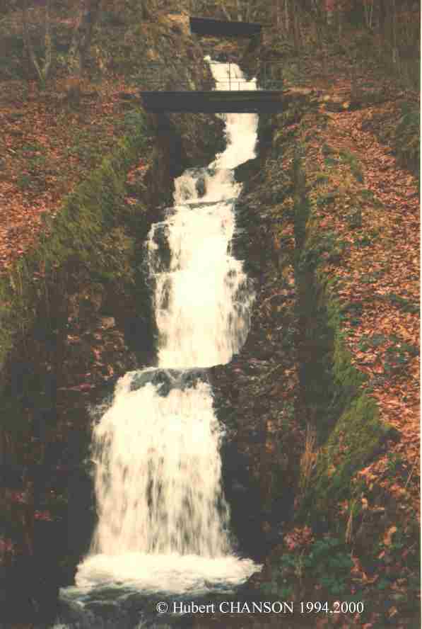
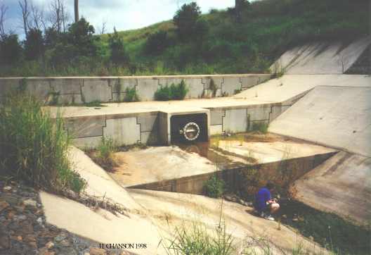
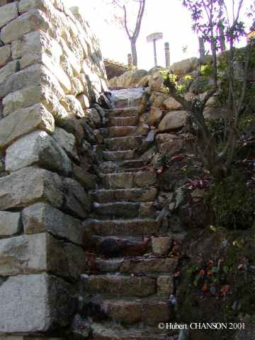
Photo No. 8 : Concrete stepped chute on
22 Sept. 2006.
Photo No. 9 : Gold Creek flood plain
downstream of the Gold Creek dam on 25 Sept. 2006; note the house in the
background sitting on inundable land : flow plain mismanagement ?
Photo No. 10 : House in the flood plain
of Gold Creek on 25 Sept. 2006.
Photo No. 11 & 12 : Gold Creek dam spillway during CIVL3140 field trip
on 5 Sept. 2007 : Photo 11 & Photo
12.
Photo No. 13 & 14: Gold Creek dam spillway during CIVL3140 field trip on
9 Sept. 2009 : students
studying the first two steps; Students
on the lower steps of the staircase spillway; Students
inspecting the broad-crest (Courtesy of Stefan FELDER).
Photo
No. 15 & 16: Overflow on 2 May 2015 after 162 mm of
rainfall in the catchment on 1 May 2015: Photo
No. 15: View from downstream; Photo
No. 16: View from the left bank.
Photo No. 17: CIVL3140 students
working on the steps of Gold Creek dam spillway on 19 April 2016.
Photo No. 18:
CIVL3140 students on the spillway crest on 19 April 2016.
Photo No. 19: Gold
Creek dam stepped chute on 19 April 2016.
Contemporary structures
Le Pont dam (France 1882). Dam
and
spillway designed by H. BAZIN. Stepped spillway with circular step crests
and pooled steps. Photograph taken in June 1998.
Goulburn weir (Victoria, Australia 1891). Photo
No. 1 : weir overflow prior to the gate refurbishment - Photo
No.
2 : View from left bank, with one opened gate (Q=5 m3/s) on 30 Jan.
2000.
La Tâche dam (France 1891). Unlined
rock stepped cascade, photograph taken in Dec. 1994. (Also called
Chartrain dam).
Croton Falls dam stepped spillway. Completed in
1911, the reservoir is part of New York City water supply system. The
stepped spillway is 213 m wide (h = 0.61 m) and it is equipped with
rounded steps (CHANSON 1995, p.
31, 39 &202). Photo No.1 and No. 2: Overflow in March 2001 (Courtesy
of Mrs J. HACKER).
Lahontan dam stepped spillway (Nevada, USA 1922). Photo No. 1 : left spillway overflow on
31 May 1922 (Courtesy of US Bureau of Reclamation and Roy WINGATE). The
left spillway consists of a series of 6 steps (h = 3.05 m, q
= 26.6 deg., W = 76.3 m), a converging flat chute section and a curved
stepped channel (3 steps, h = 3.05 m, l = 6.096 m, W = 45.72 m) with a
curvature radius ranging from 39 to 50 m. Note the training walls. Photo
No.
2 : aerial view of the dam and spillway in 1972 (Courtesy of US
Bureau of Reclamation and Brit STOREY).
Timber crib weirs
Whetstone weir (Inglewood QLD, Australia
1951) at low flow (H. CHANSON, Feb. 1998) - Timber crib
stepped weir (H = 5 m) on the Macintyre Brook, completed in 1951. A
major flood occurred in 1956, the maximum recorded stream height being
11.8 m at Inglewood.
Silverleaf weir (Murgon QLD, Australia
1953) (H. CHANSON, Nov. 1997) - Timber crib stepped weir
(H = 5.1 m) on the Barambah Creek. More about Timber
crib
weirs ...
Cunningham weir (Texas QLD, Australia
1953) in operation (H. CHANSON, Feb. 1998) - Timber-crib
stepped weir (H = 4 m) on the Dumaresq river, completed in 1954. During
a major flood in 1956, the maximum recorded head-above-crest reached 7.3
m. The weir was little damaged and it is still in use. See listing in Structurae.
Greenup weir (Inglewood QLD, Australia
1958) at low flow (H. CHANSON, Feb. 1998) - Timber crib
stepped weir (H = 5 m) on the Macintyre Brook, completed in 1958,
upstream of Whetstone weir. More about Timber
crib
weirs ...
Modern stepped spillway systems
New Croton dam stepped spillway (New York NY, USA 1955). Photo No. 1 : in July 1999 (Courtesy
of Mrs J. HACKER) (Ref.: CHANSON
1995, Pergamon, pp. 189-191).
Joe Sippel weir (Murgon QLD,
Australia) in November 1997 (H. CHANSON) - Completed in
1984, the 6.5-m high stepped weir is used for irrigation and water
regulation purposes. The structure was built of steel sheet piles and
concrete slabs. It is located upstream of the Silverleaf
weir.
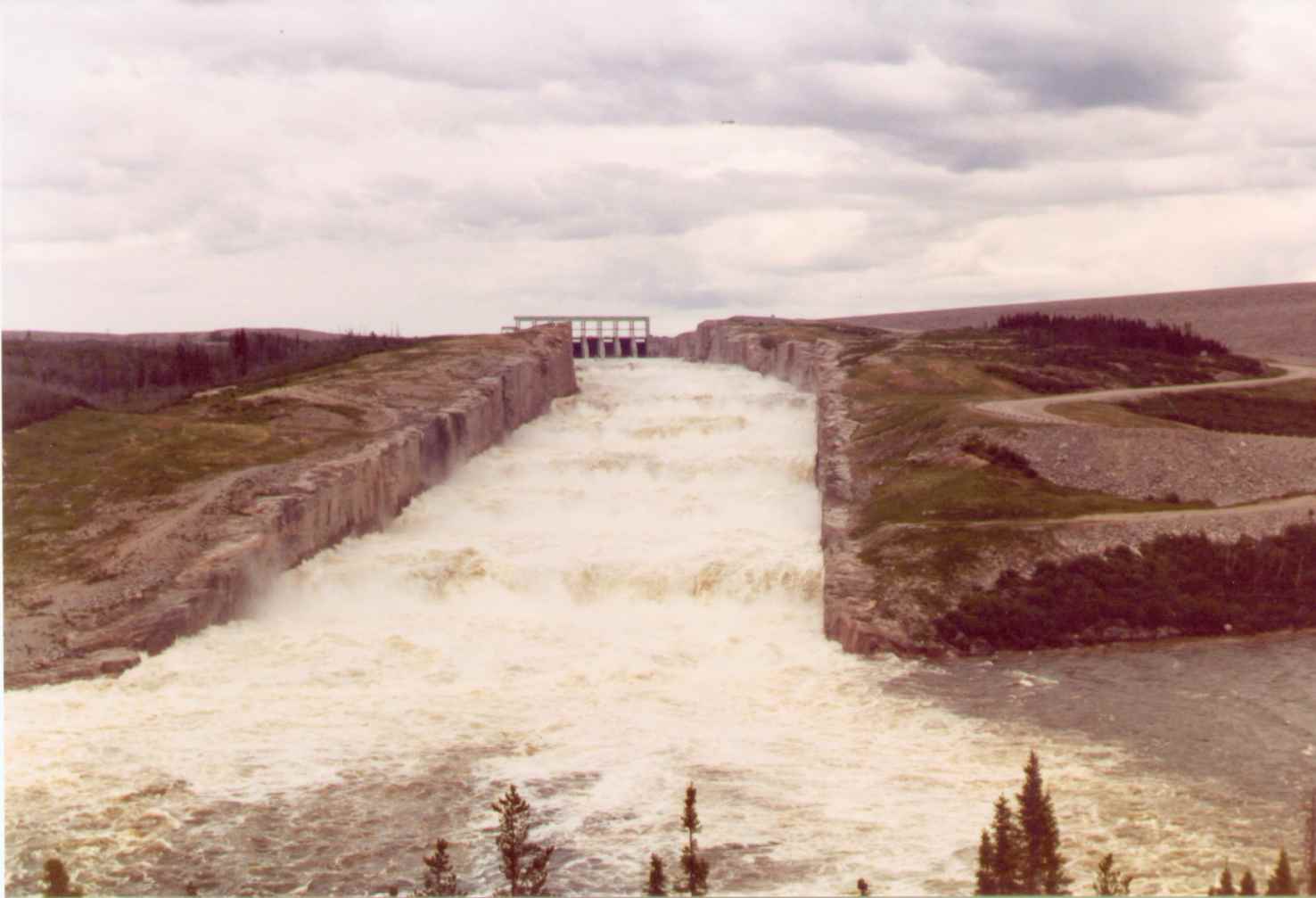
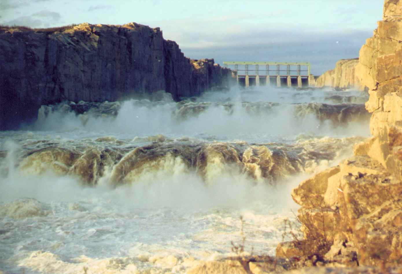
La Grande 2 spillway (Québec,Canada) - Unlined
rock stepped cascade in operation in 1983: Photo
No.
1, view from downstream (Courtesy of Michel Lefebvre) - Photo
No.
2 : view of the upstream steps (Courtesy of Michel Lefebvre).
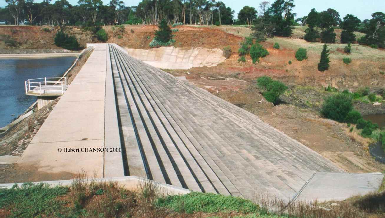
Melton dam overflow stepped spillway (Melton VIC, Australia 1916).
The Melton dam is an earthfill structure. Completed in
1916, the dam was heightened twice because of the rapid reservoir
siltation. During the last refurbishment in 1994, an overflow stepped
spillway was added. Photo No. 1 :
general view (30 Jan. 2000). Photo No.
2 : details of the dam overflow spillway (30 Jan. 2000). More
about Extreme reservoir siltation
...
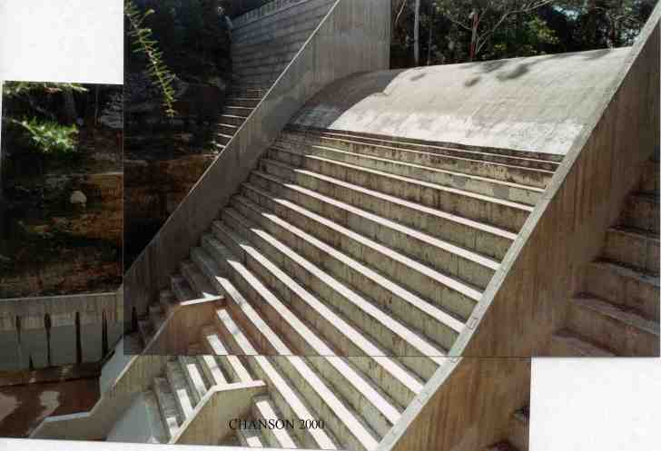
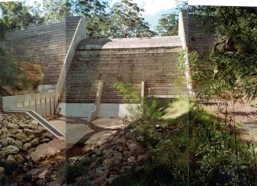
Riou dam (France 1990). RCC stepped spillway : h =
0.43 m. Photo No. 1 : view from
downstream at sunset (photograph taken in Nov. 1994). Photo
No.
2 : view from right bank (photograph taken in Nov. 1994). Photo
No.
3 : view from the right bank of the crest, chute and stilling
basin in June 1998. Photo No. 4 :
view from downstream in June 1998. More
information ...
Santa Cruz arch dam stepped spillway
(New Mexico, USA). Completed in 1929, the Santa Cruz dam
was a masonry arch dam. In 1987, the dam was reinforced by concrete
buttresses and roller compacted concrete. A new overflow stepped
spillway was built between two buttresses (Design: 56 m3/s) (Courtesy of
US Bureau of Reclamation and John LABOON). More
information ...
Jordan II weir (Gatton QL, Australia
1992). Reinforced-earth stepped overflow weir (H = 5.3
m). Photograph in Feb. 1998.
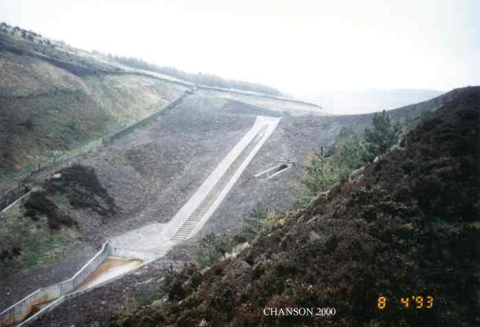
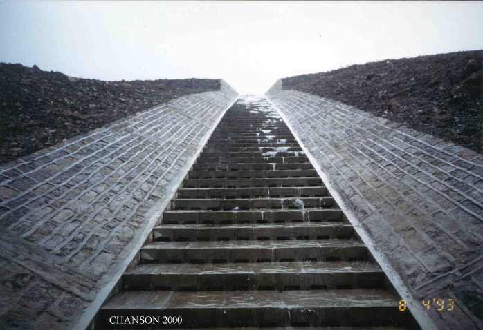
Brushes Clough dam spillway (1859-1991). Overflow
embankment spillway system with precast concrete blocks. Photo
No.
1 : General view in 1993 (Courtesy of Mr GARDINER, NWW). Photo
No.
2 : details of the concrete blocks, showing the drainage holes
(Courtesy of Mr GARDINER). More about Embankment
overflow
stepped spillways: earth dam spillways with precast concrete blocks...
Zaraysk dam (also called Laraisky),
Russia (Courtesy of Prof. Y. PRAVDIVETS). Overflow
embankment spillway made of precast concrete blocks.
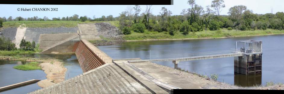
Loyalty Road Flood Retarding dam spillway (Sydney NSW, Australia,
1996) - Photo No. 1 :
view from the right bank (Courtesy of D.Patrick JAMES). Photo
No.
2 : view from downstream (Courtesy of D.Patrick JAMES). Dam height
: 30 m. RCC construction. Spillway capacity : 1,040 m3/s. Chute width :
30 m.
Bucca weir (Bucca QLD, Australia 1987)
(H. CHANSON, 23 Dec. 2001). RCC irrigation weir on the
Kolan river.
Neil Turner weir (Mitchell QLD, Australia 1984). 5.9
m
high stepped weir on the Maranoa river. Photo
No.
1 : general view in July 2001 (Courtesy of Chris PROCTOR). Photo
No.
2 : detail of steps in July 2001 (Courtesy of Chris PROCTOR).
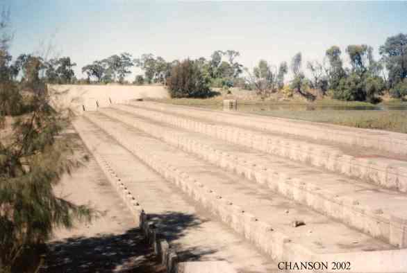
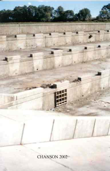
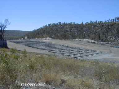
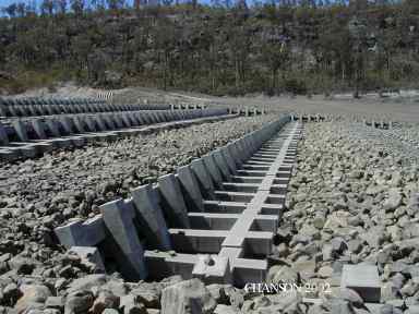
Artifical stepped cascade at Biloela (QLD, Australia).
Design flow: 390 m3/s, step height: 2 m, width: 100 m. Photo
No.
1 : General view shortly after construction in 2002 (Courtesy of
Dr John MACINTOSH). Photo No. 2 :
View of a step arrangement, from the right bank (Courtesy of Dr John
MACINTOSH). Photo No. 3 :
1:16 scale model, based upon a Froude similitude (Courtesy of Dr John
MACINTOSH). Photo No. 4 : physical
model in operation for Q = 10 L/s (20 m3/s prototype); all the water
flows as seepage; the colours are paint sprayed on the rockfill to
visualise erosion and scour. Photo No.
5 : physical model in operation for Q = 103 L/s (210 m3/s
prototype); note overflows and seepage, and the hydraulic jump
downstream of the plunge point.
Hinze dam spillway
(Stage 3). Operation on 29/1/2013 at 12:15, Q ~ 170 m3/s. Photo No. 1: View from downstream of
the stepped spillway operation. Photo
No. 2: View from upstream of the uncontrolled ogee and stepped chute
operation. See also: "Interactions between a Developing Boundary Layer and
the Free-Surface on a Stepped Spillway: Hinze Dam Spillway Operation in
January 2013", Proc. 8th International
Conference on Multiphase Flow ICMF 2013, Jeju, Korea, 26-31 May,
Gallery Session ICMF2013-005 (Video duration: 2:15). (Description)
(Record
at
UQeSpace) (Video
movie at UQeSpace). Site visit with CIVL4120 Advanced hydraulics
students on 24 October 2014: Photo
No.11: general view of stepped spillway and stilling basin. Photo No. 12:
stilling basin and turning veins leading to an ogee weir. Photo No. 13: stepped spillway with
3.3 m high baffle blocks in the foreground. Photo
No. 14: details of baffle block. Photo
No. 15: engineering students discussing about the spillway system
next to a baffle block. Photo
No. 16: CIVL4120 students with Professor Chanson at the spillway
toe. Photo No. 17:
stepped spillway toe and stilling basin. Small overflow on 3 May 2015: Photo No. 18: View
from downstream; Photo
No. 19: View from upstream, with flow direction from top to bottom.
Paradise dam, Biggeden
QLD (Australia) - RCC gravity dam equipped with an uncontrolled
stepped spillway. Photo
No. 1: General view of the spillway on 5 March 2013. Photo No. 2: View of the spillway and
stilling basin operation on 5 March 2013. Photo
No. 3: Details of the free-surface next to the inception of
free-surface aeration on the stepped spillway on 5 March 2013. Photo
No. 4: turbulence and air-water flow in the stilling basin on 5
March 2013.
Stepped storm waterway systems
Storm waterway at Miya-jima (Japan) - Photo
No.
1 : storm waterway below below Senjò-kaku wooden hall on 19 Nov.
2001. The stepped chute is steep (slope > 45 deg., h ~ 0.4 m). The
Senjò-kaku wooden hall was built by Kyomori (AD 1168) and left
unfinished at his death. It is likely that the waterway design dates
from the 12th century.
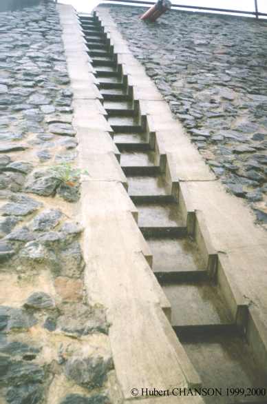
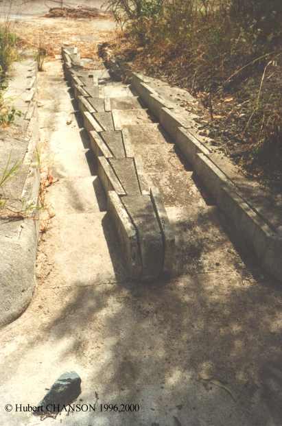
Stepped road gutter systems : another application
of the stepped chute design. Photo No.
1 : steep gutter along the Western freeway, Brisbane (Photograph
taken in Dec. 1999). Photo No. 2 :
double road gutter looking downstream, next to Sumner Rd freeway
entrance, between Darra and Mt Ommaney, Brisbane (Photogaph taken in
Nov. 1996).
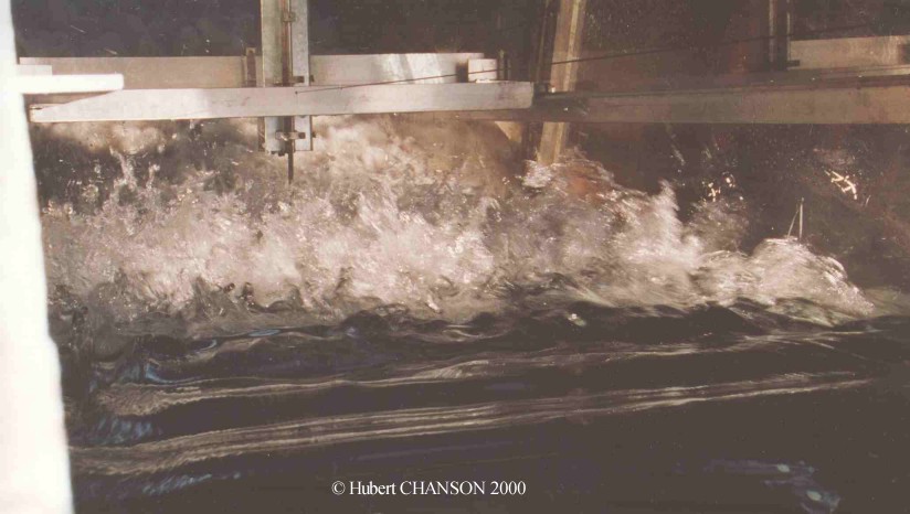
Research onto stepped spillway hydraulics
Research on stepped spillways at UQ : 22º slope, h = 0.10 m, l =
0.25 m, W = 1 m, q = 0.103 m2/s, dc/h = 1.0. Photo
No.
1 : View from upstream looking towards the inception point of air
entrainment. Photo No. 2: Side view
(Y90 = 0.078 m, Cmean = 0.48, Fmax = 149 Hz at the probe location)
(Photographs taken on 7 July 2000). Photo
No. 3 : dc/h = 1.5 (flow from left to right, run Q23).
Photo No. 4 : dc/h = 1.1
(run Q21). Photo No. 5 : dc/h
= 0.7 (run Q22). (Download
the full results as PDF files : Part 1
and Part 2)
Research on stepped spillways at UQ : 16º slope, h = 0.10 m, l =
0.35 m, W = 1 m. Photo
No. 1 : Nappe flow (without hydraulic jump NA3) for dc/h = 0.64.
Related
links
 References
CHANSON, H. (2001). "The Hydraulics of Stepped
Chutes and Spillways." Balkema,
Lisse, The Netherlands (ISBN 90 5809 352 2). Order
form. Corrections
and
Updates
CHANSON, H. (2001b). "Teaching Hydraulic Design in an Australian
Undergraduate Civil Engineering Curriculum." Jl of Hyd. Engrg.,
ASCE, Vol. 127, No. 12, pp. 1002-1008 (ISSN 0733-9429). (Download
PDF File)
CHANSON, H. (2004). "Enhancing Students' Motivation in the Undergraduate
Teaching of Hydraulic Engineering: the Role of Field Works" Jl
of Prof. Issues in Engrg Educ. and Practice, ASCE, Vol. 130, No. 4,
pp. 259-268 (ISSN 0733-9380). (Download
PDF file)
CHANSON, H., and WHITMORE, R.L. (1996). "Investigation of the Gold Creek Dam
Spillway, Australia." Research Report No. CE153, Dept. of Civil
Engineering, University of Queensland, Australia, 60 pages (ISBN 0 86776 667
0). (PDF
file at UQeSpace)
CHANSON, H., and WHITMORE, R.L. (1998). "Gold Creek Dam and its Unusual
Waste Waterway (1890-1997) : Design, Operation, Maintenance." Can. Jl of
Civil Eng., Vol. 25, No. 4, Aug., pp. 755-768 and Front
Cover (ISSN 0315-1468). (download PDF file)
COSSINS, G. (2000). "The Gold Creek Dam Story." Inst. of Engineers,
Australia, Queensland Div., Brisbane, Australia.
WHITMORE, R.L. (1996). "Gold Creek Reservoir. Its Heritage and
Conservation." Report to the Brisbane City Council, Brisbane,
Australia, 2 sections.
WHITMORE, R.L. (1997). "Queensland's Early Waterworks." Department of
Natural Resources Queensland, Brisbane, Australia, 190 pages.
Bibliography
CHANSON, H. (1997). "Air Bubble
Entrainment in Free-Surface Turbulent Shear Flows." Academic Press,
London, UK, 401 pages (ISBN 0-12-168110-6).
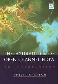
CHANSON, H. (1999). "The
Hydraulics
of Open Channel Flows : An Introduction." Butterworth-Heinemann,
London, UK, 512 pages (ISBN 0 340 74067 1).
CHANSON, H. (2000-2001). "Historical Development of Stepped Cascades for the
Dissipation of Hydraulic Energy." Trans. Newcomen Society, Vol. 71,
No. 2, pp. 295-318 (ISSN 0372-0187). (Download PDF
File)
CHANSON, H., and TOOMBES, L. (1997). "Flow Aeration at Stepped cascades." Research
Report No. CE155, Dept. of Civil Engineering, University of
Queensland, Australia, June, 110 pages (ISBN 0 86776 730 8). (PDF
version at EprintsUQ)
CHANSON, H. (2001). "Hydraulic Design of Stepped Spillways and Downstream
Energy Dissipators." Dam Engineering, Vol. 11, No. 4, pp. 205-242
(ISSN 0 617 00563 X). (Download PDF
File)
CHANSON, H., and TOOMBES, L. (2001). "Experimental Investigations of Air
Entrainment in Transition and Skimming Flows down a Stepped Chute.
Application to Embankment Overflow Stepped Spillways." Research Report
No. CE158, Dept. of Civil Engineering, The University of Queensland,
Brisbane, Australia, July, 74 pages (ISBN 1 864995297). (Download
PDF
files : Part 1 and Part
2)
GONZALEZ, C.A., TAKAHASHI, M., and CHANSON, H. (2005). "Effects of Step
Roughness in Skimming Flows: an Experimental Study." Research
Report No. CE160, Dept. of Civil Engineering, The University of
Queensland, Brisbane, Australia, July, 149 pages (ISBN 1864998105). (Download
PDF File) (PDF
Version at EprintsUQ)
ZHANG, G., and CHANSON, H. (2018). "Effects of Step and Cavity Shapes on
Aeration and Energy Dissipation Performances of Stepped Chutes." Journal
of Hydraulic Engineering, ASCE, Vol. 144, No. 9, Paper 04018060, 12
pages (DOI: 10.1061/(ASCE)HY.1943-7900.0001505) (ISSN 0733-9429). (PDF file) (Preprint at
UQeSpace)
Video movies at UQeSpace
CHANSON, H. (2020). "Hydraulics of open channel flow: practical
experiments at the University of Queensland, Australia." Collection, Generic
Document, The University of Queensland, School of Civil Engineering,
Brisbane, Australia (ISBN 978-1-74272-311-2). {https://espace.library.uq.edu.au/collection/UQ:734960}
EDLIN, S., LU, Z., and CHANSON, H. (2020). "The
Broad-Crested Weir." Generic Document, The University of Queensland, School
of Civil Engineering, Brisbane, Australia (ISBN 978-1-74272-311-2). {https://espace.library.uq.edu.au/view/UQ:734961}
SHI, S., ASTORGA MOAR, A., and CHANSON, H. (2020). "The
Hydraulic Jump." Generic Document, The University of Queensland, School of
Civil Engineering, Brisbane, Australia (ISBN 978-1-74272-311-2). {https://espace.library.uq.edu.au/view/UQ:734962}
LI, Y., LANCASTER, O., and CHANSON, H. (2020). "Backwater
in a Long Channel." Generic Document, The University of Queensland, School
of Civil Engineering, Brisbane, Australia (ISBN 978-1-74272-311-2). {https://espace.library.uq.edu.au/view/UQ:734963}
WUTHRICH, D., WUPPUKONDUR, A., and CHANSON, H. (2020).
"Hydraulics of Culverts." Generic Document, The University of Queensland,
School of Civil Engineering, Brisbane, Australia (ISBN 978-1-74272-311-2). {https://espace.library.uq.edu.au/view/UQ:734964}
Acknowledgments
The writer acknowledges the asssitance of Professor R.L. WHITMORE, Geoff
COSSINS and R. TUMMAN.
License

This work is licensed under a Creative
Commons Attribution-NonCommercial 3.0 Unported License.
Hubert
CHANSON is a Professor in Civil Engineering, Hydraulic Engineering
and Environmental Fluid Mechanics at the University
of Queensland, Australia. His research interests include design of
hydraulic structures, experimental investigations of two-phase flows,
applied hydrodynamics, hydraulic engineering, water quality modelling,
environmental fluid mechanics, estuarine processes and natural resources.
He has been an active consultant for both governmental agencies and
private organisations. His publication record includes over 950
international refereed papers and his work was cited over 5,000 times
(WoS) to 19,500 times (Google
Scholar) since 1990. His h-index is 40 (WoS), 44 (Scopus) and 70 (Google
Scholar), and he is ranked among the 150 most cited researchers in
civil engineering in Shanghais
Global Ranking of Academics. Hubert Chanson is the author of twenty
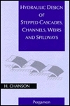
books, including "Hydraulic Design
of Stepped Cascades, Channels, Weirs and Spillways" (Pergamon,
1995), "Air Bubble Entrainment in
Free-Surface Turbulent Shear Flows" (Academic
Press, 1997), "The Hydraulics
of Open Channel Flow : An Introduction" (Butterworth-Heinemann,
1st edition 1999, 2nd
editon 2004), "The Hydraulics of
Stepped Chutes and Spillways" (Balkema,
2001), "Environmental
Hydraulics of Open Channel Flows" (Butterworth-Heinemann,
2004), "Tidal
Bores, Aegir, Eagre, Mascaret, Pororoca: Theory And Observations" (World
Scientific, 2011) and "Applied
Hydrodynamics:
an Introduction" (CRC
Press, 2014). He co-authored two further books "Fluid Mechanics for
Ecologists" (IPC Press, 2002) and "Fluid Mechanics for Ecologists.
Student Edition" (IPC, 2006). His
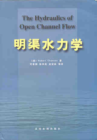
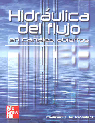
textbook "The Hydraulics of Open Channel Flows : An Introduction" has
already been translated into Spanish (McGraw-Hill
Interamericana) and Chinese (Hydrology Bureau of Yellow
River Conservancy Committee), and the second
edition was published in 2004. In 2003, the IAHR
presented him with the 13th Arthur Ippen Award
for outstanding achievements in hydraulic engineering. The American
Society of Civil Engineers, Environmental and Water Resources Institute
(ASCE-EWRI) presented him with the 2004 award for the Best Practice paper
in the Journal of Irrigation and Drainage Engineering ("Energy
Dissipation
and Air Entrainment in Stepped Storm Waterway" by Chanson and
Toombes 2002) and the 2018 Honorable Mention Paper Award for "Minimum Specific
Energy and Transcritical Flow in Unsteady Open-Channel Flow" by
Castro-Orgaz and Chanson (2016) in the ASCE Journal of Irrigation and
Drainage Engineering. The Institution of Civil Engineers (UK) presented
him the 2018 Baker Medal. In 2018, he was inducted a Fellow of the Australasian Fluid Mechanics Society.
Hubert Chanson edited further several books : "Fluvial,
Environmental and Coastal Developments in Hydraulic Engineering"
(Mossa, Yasuda & Chanson 2004, Balkema),
"Hydraulics.
The
Next Wave" (Chanson & Macintosh 2004, Engineers
Australia), "Hydraulic
Structures:
a Challenge to Engineers and Researchers" (Matos & Chanson 2006,
The University of Queensland), "Experiences and
Challenges in Sewers: Measurements and Hydrodynamics" (Larrate &
Chanson 2008, The University of
Queensland), "Hydraulic
Structures:
Useful Water Harvesting Systems or Relics?" (Janssen & Chanson
2010, The University of Queensland),
"Balance
and Uncertainty: Water in a Changing World" (Valentine et al. 2011,
Engineers Australia), "Hydraulic
Structures and Society Engineering Challenges and Extremes"
(Chanson and Toombes 2014, University
of Queensland), "Energy
Dissipation
in Hydraulic Structures" (Chanson 2015, IAHR
Monograph, CRC Press). He chaired the Organisation of the 34th
IAHR World Congress held in Brisbane, Australia between 26 June and
1 July 2011. He chaired the Scientific Committee of the 5th IAHR
International Symposium on Hydraulic Structures held in Brisbane in
June 2014. He chairs the Organisation of the 22nd Australasian Fluid
Mechanics Conference in Brisbane, Australia on 6-10 December 2020.
His Internet home page is http://www.uq.edu.au/~e2hchans.
He also developed a gallery of photographs website {http://www.uq.edu.au/~e2hchans/photo.html}
that received more than 2,000 hits per month since inception.
More pictures of stepped spillways are here
...
TECHNICAL INTERNET RESOURCES
More about a history of arch dams
... More about timber crib
weirs ... More about steel
dams ...
More about engineering
failures ... More about rubber
dams ... More about a tidal
bore ...
More about the Formal Water Garden
.... More about rapid
reservoir sedimentation in Australia ...
More about Minimum Energy Loss culverts
.. More about Minimum Energy
Loss weirs ...
This page was visited : 8,207 times between
18-06-2002 and June 2012.
Last updated on 20/06/2018

