|
|
|
|
|
|
|
|
In the coastal plains of Queensland (North-East of Australia), torrential rains during the wet season place a heavy demand on culverts. Further the natural slope of the flood plains is often very small (So ~ 0.001) and little fall (or head loss) is permissible in the culverts. Professors G.R. McKAY and C.J. APELT developed and patented the design procedure of minimum energy loss waterways. Professor C.J. APELT presented an authoritative review of the topic (APELT 1983) and a well-documented documentary (APELT 1994).
A Minimum Energy Loss culvert or waterway is a structure designed with
the concept of minimum head loss. The flow in the approach channel is
contracted through a streamlined inlet into the barrel where the channel
width is minimum, and than it is expanded in a streamlined outlet before
being finally released into the downstream natural channel. Both the inlet
and outlet must be streamlined to avoid significant form losses. The
barrel invert is often lowered to increase the discharge capacity (see Photographs). APELT (1983) presented an
authoritative review of the topic. CHANSON discussed the wide range of
design options (CHANSON 2000) and he showed
detailed illustrations (CHANSON 1999, pp.
363-368, 383-397, & 421-430).
Basic design concepts
The basic concepts of MEL culvert design are : streamlining and critical
flow conditions throughout all the waterway (inlet, barrel, outlet) (APELT
1983, CHANSON 1999,2000).
Streamlining : The intake is designed with a smooth contraction into the barrel while the outlet, also called diffuser, is shaped as a smooth expansion back to the natural channel. The 'smooth' shapes should reduce the head losses (compared with a standard culvert) for the same discharge and barrel width. Practically small head losses are achieved by streamlining the inlet and outlet forms : i.e., the flow streamlines will follow very smooth curves and no separation is observed (1).
Critical flow conditions : In an open channel, maximum discharge per unit
width for a given specific energy is achieved at critical flow conditions.
Minimum Energy Loss structures are designed to achieve critical flow
conditions IN ALL THE ENGINEERED WATER WATERWAY. That is, in the inlet, at
the throat (or barrel) and in the outlet. At the throat, the discharge per
unit width q may be increased by lowering the barrel bed while satisfying
the Bernoulli principle (2).
 Historical
developments
Historical
developments
The concept of Minimum Energy Loss culverts was developed by Norman
COTTMAN, shire engineer in Victoria (Australia) and by Professor Gordon
McKAY, University of Queensland (Brisbane, Australia) during the late
1960s (CHANSON 2003). While a number of
small-size structures were designed and built in Victoria, some major
structures were designed, tested and built in South-East Queensland.
The largest Minimum Energy Loss waterway is the Nudgee Road MEL waterway
near the Brisbane airport with a design discharge capacity of 800 m3/s.
Built between 1968 and 1970, the waterway design tested in laboratory with
a 1:48 scale model. Since completion, the structure passed successfully
floods and it is still in use. An unusual construction feature is the
grass-lined channel bed. Several Minimum Energy Loss culverts were built
in Southern Brisbane during the construction of the South-East Freeway,
along Norman Creek in 1974-1975. The design discharge capacity range from
200 to 250 m3/s. All the structures are still in use today (Photographs
1,2, 4 & 5). A MEL culvert (Qdes = 60 m3/s) was built at Jerry's
Downfall in southern Brisbane in 1970. (The structure no longer exists).
McKAY (1971) indicated further MEL culverts
built in Northern Territory near Alice springs in 1970.
 Footnotes
(1) The shape of the standard and MEL culverts can be respectively
compared to a sharp-edge orifice and a Venturi-meter in a circular pipe.
At an orifice, large head losses take place in the recirculation region
immediately downstream of the orifice as for a standard culvert. In the
Venturi-meter, the flow is streamlined and very small head losses are
observed. From a top view, the MEL culvert sidewalls follow usually the
shape of a Venturi meter. As for a Venturi meter, the angle between
straight diverging walls and the waterway centreline should be less than
about 8 degrees (for straight wing wall outlets).
The inlet and outlet may be designed using a flow net analysis and the
"potential flow theory" (e.g. VALLENTINE 1969).
The contour lines (i.e. lines of constant invert elevation) are the
equi-potentials which must be perpendicular to the streamlines
everywhere.The wingwalls are streamlines and the complete flow net may be
drawn by test and trial (e.g. VALLENTINE 1969, pp. 77-87).
(2) At critical flow conditions, the culvert barrel invert excavation
yields an increase in specific energy according to the Bernoulli principle
(CHANSON 1999,2004). The associated increase in critcial flow depth (Emin
= 2/3*dc) induces an increase in flow rate per unit width : q =
sqrt(g*dc3).
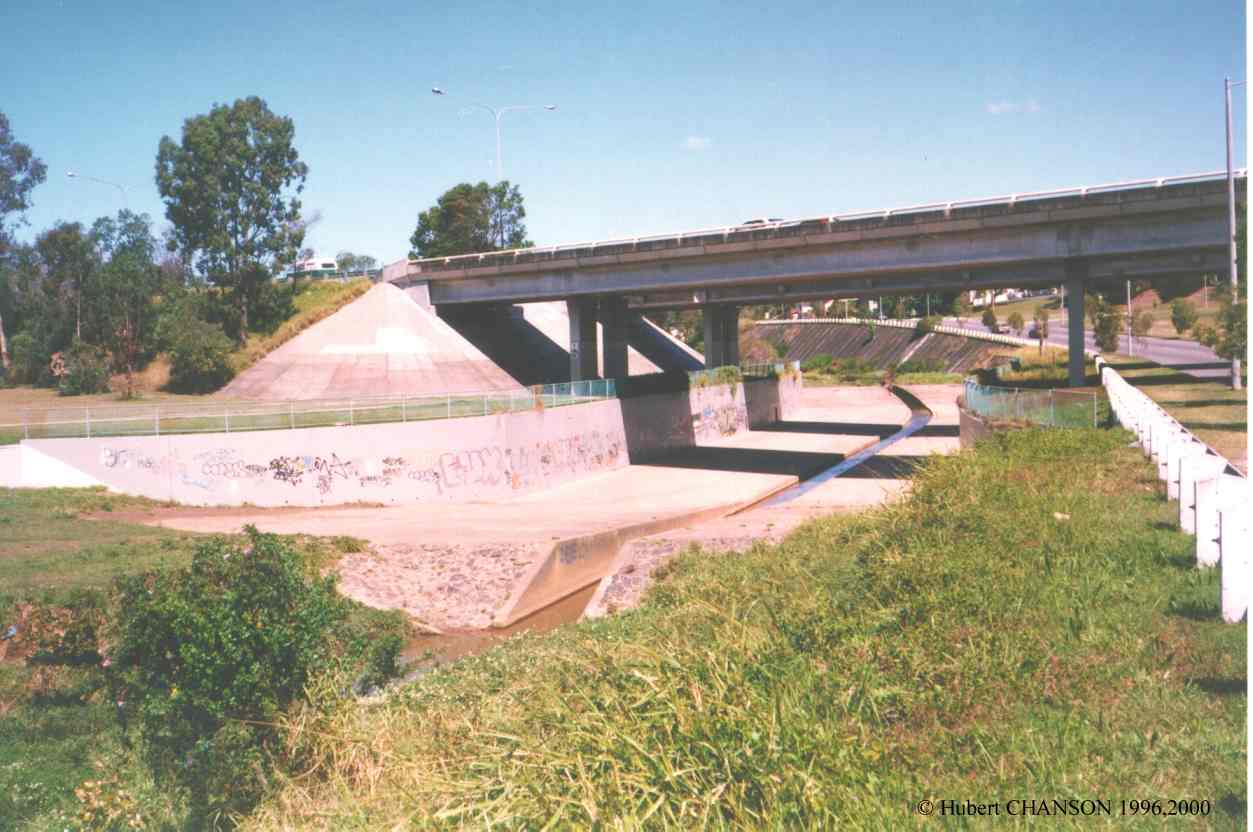
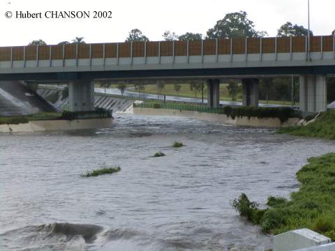
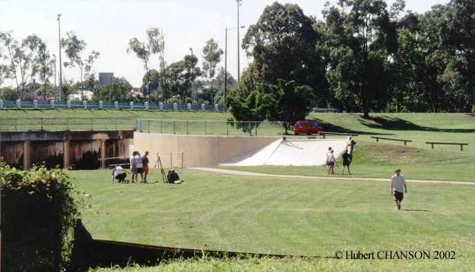
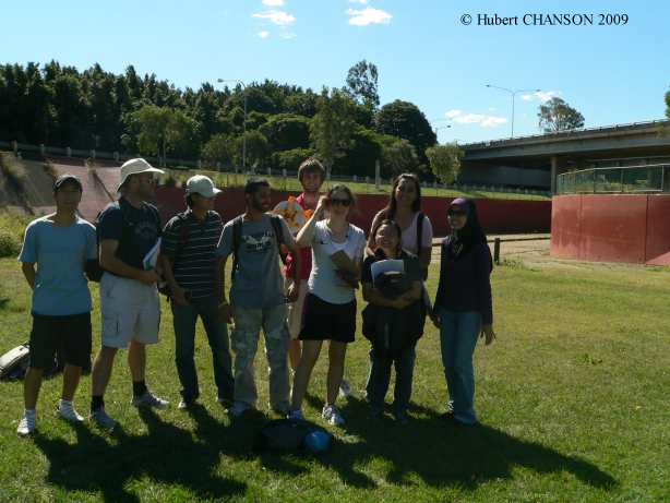
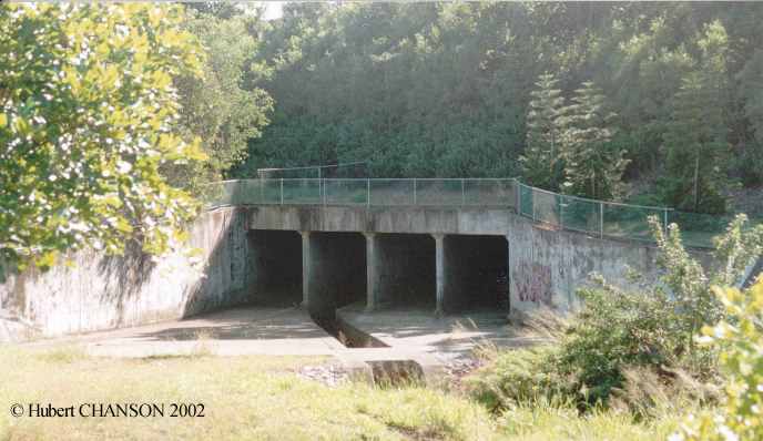
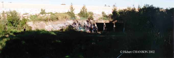
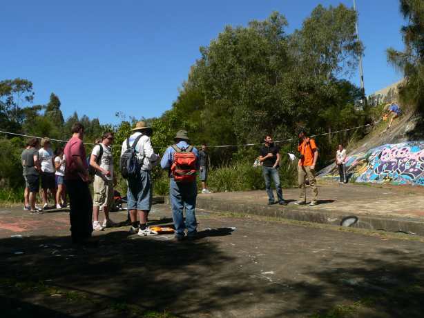
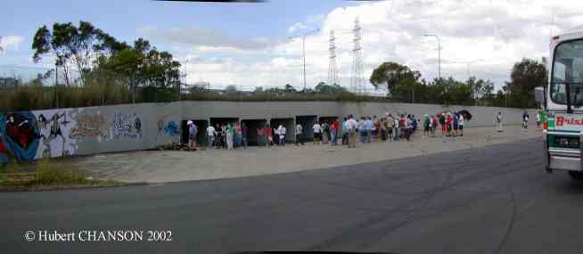
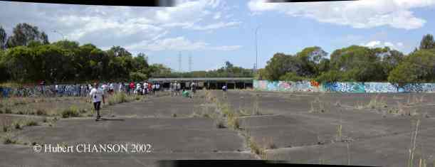
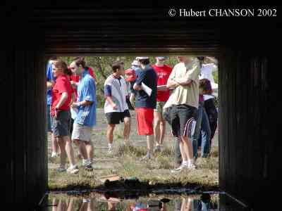
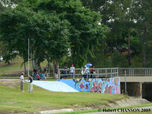
Photo No. 2 : Outlet and barrel of a MEL waterway along Norman Creek, under the South-East freeway and parallel to Ridge St (Brisbane QLD, Australia). Looking upstream. MEL waterway No. MEL-W-1 (CHANSON 1999, pp. 421-430). Design discharge : 200 m3/s, Barrel width : 10 m. Outlet operation (view from downstream) on 31 Dec. 2001 after a rainstorm (Q ~ 60-70 m3/s). Field trip by CIVL4510 students (where are they?) on 13 May 2002. CIVL3140 student field trip on 9 Sept. 2009: student group in front of the inlet.
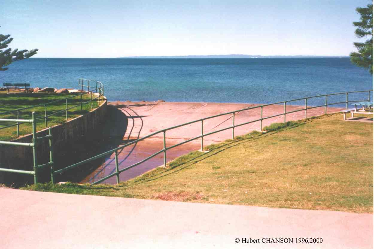
Photo No. 3 : Outlet of the MEL culvert at Redcliffe (QLD, Australia) between the shopping centre and the sea. View of the outlet looking at the Moreton Bay. MEL culvert No. MEL-C-6 (CHANSON 1999, pp. 421-430). Design discharge : 36 m3/s, Barrel width : 5.5 m, Barrel length : 137 m, Invert drop : 1.2 m.
Photo No. 4 : MEL culvert No. MEL-C-2 (CHANSON 1999, pp. 421-430). Design discharge : 220 m3/s. Located along Norman Creek underneath SE Freeway parallel to Birdwood St, Brisbane (Australia). Inlet, looking from the left bank on 13 May 2002.
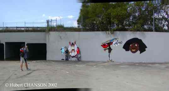
Photo No. 5 : MEL culvert No. MEL-C-X2 (CHANSON 2004), Ekibin Park, on Norman Creek. Design discharge : 220 m3/s. Built in 1971. Located underneath South-East Freeway. Inlet survey during Field survey CIVL4510 on Mon 13 May 2002. CIVL3140 student field trip on 9 Sept. 2009: Inlet of the MEL culvert, looking upstream; Outlet of of the MEl culvert.
Photo No. 6 : MEL culvert No. MEL-C-4 (CHANSON 1999). Design discharge : ~220 m3/s. MEL culvert beneath the Gateway motorway (Brisbane, Australia). Photo No. 6a : inlet on 11 Sept. 2002 during CIVL3140 student field trip. Photo No. 6b : inlet wingwall on 11 Sept. 2002 during CIVL3140 student field trip.
Photo No. 7 : MEL culvert No. MEL-C-5 (CHANSON
1999). Design discharge : ~100 m3/s. MEL culvert beneath the Gateway
motorway (Brisbane, Australia). Photo No.
7a : inlet on 11 Sept. 2002 during CIVL3140 student field trip. Photo No. 7b : students in inlet
channel on 11 Sept. 2002 during CIVL3140 student field trip. Photo
No. 7c : students at the dowsntream end of the barrel on 11 Sept.
2002 during CIVL3140 student field trip.
Photo No. 8: CIVL3140 students in
a MEL culvert barrel on 19 April 2016.
Photo No. 10:
MEL culvert outlet on 19 April 2016 during CIVL3140 field trip.
Norman Creek flood flow on 7
November 2004
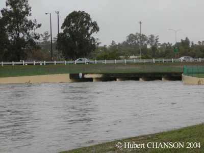
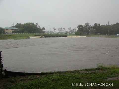
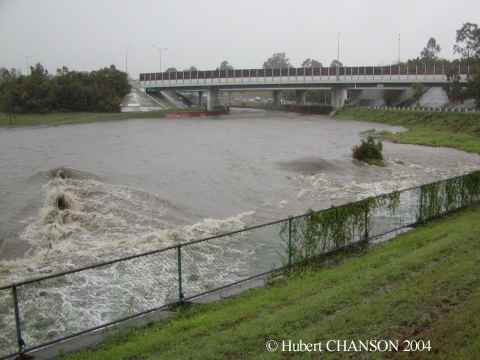
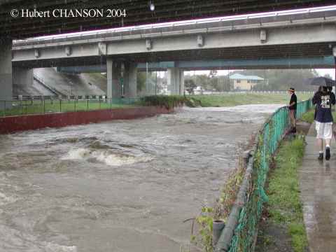
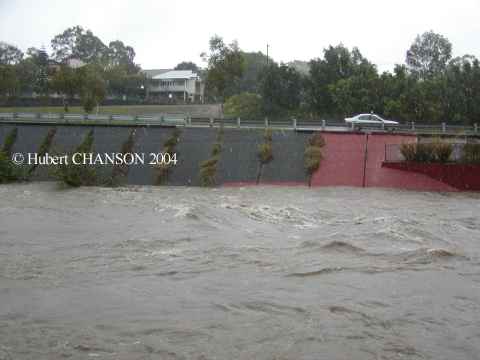
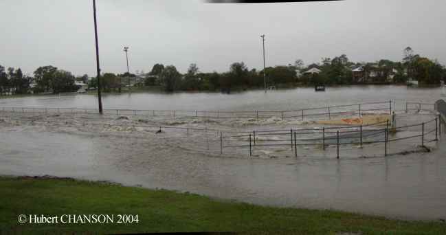
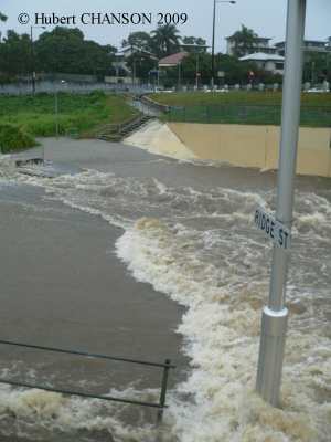
Photographs No. 21 to 27 : Flood flow (80-100 m3/s) after 60-150 mm of
rainfall in less than 3 hours. Photo No.
20: outlet of the Ridge St MEL culvert (MEL-C-3) on 7 Nov. 2004,
looking upstream; Photo No. 22: inlet
operation, looking downstream (Ridge St MEL culvert (MEL-C-3) on 7 Nov.
2004); Photo No. 23: inlet operation,
looking upstream from the culvert embanment (Ridge St MEL culvert
(MEL-C-3) on 7 Nov. 2004); note the MEL waterway No. MEL-W-1 in
background; Photo No. 24: MEL water
MEL-W-1 barrel in operation on 7 Nov. 2004, looking downstream; note the
standing wave flow; Photo No. 25:
inlet operation, view from right bank (MEL waterway (MEL-W-1) on 7 Nov.
2004); Photo No. 26: outlet
operation, looking upstream (MEL waterway (MEL-W-1) on 7 Nov. 2004); Photo
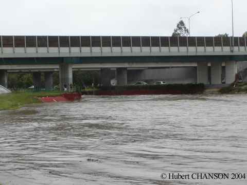
No. 27: creek operation between Ridge St and Juliette St on 7 nov.
2004, flow from right to left; note supercritical flow beneath the bicycle
bridge, and shock waves downstream of the bridge.
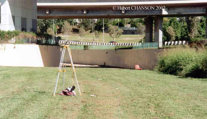
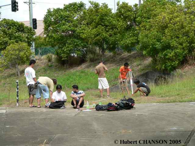
Norman Creek field survey on 11
April 2005
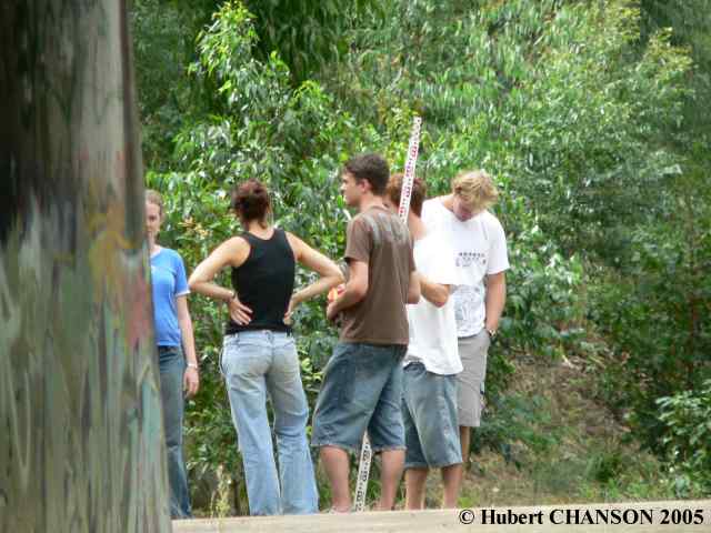
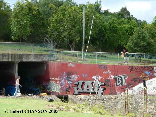
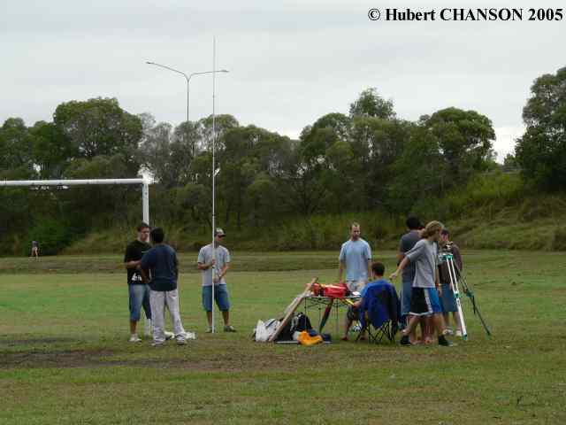
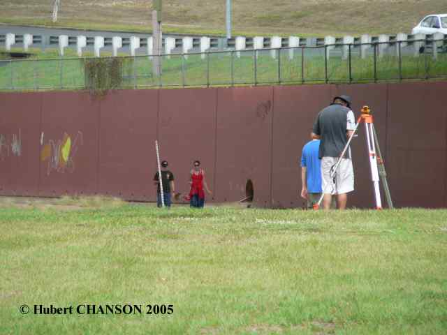
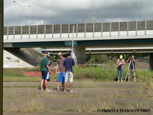
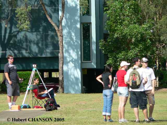
Group 1 : students surveying the Birdwood St MEL culvert inlet, looking upstream from the barrel. Group 2 : student discussion in the Ekibin MEL culvert inlet. Group 3 : survey preparation, downstream of the Ekibin MEL culvert outlet. Group 4 : field work preparation. Group 5 : survey of the MEL waterway beneath the SE freeway. Group 6 : survey of the Ridge St MEL culvert inlet. Group 8 : flood plain survey downstream of Juliette St. Group 9 : student survey of Cornwall St culvert.
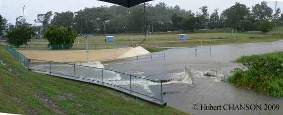
Norman Creek floods on 20 May
2009
Culvert operation during the floods on 20 May 2009: Photo
No.1: inlet operation around 09:10. Photo
No.2: inlet operation at 11:00; note the larger flow rate through
the culvert and the hydraulic jump roller in the foreground.
 References
| {http://www.uq.edu.au/~e2hchans/civ3140.html} |
UQ subject CIVL3140 Introduction of
Open Channel Flow |
| {http://www.uq.edu.au/~e2hchans/photo.html} |
Gallery of photographs in hydraulic
engineering and environmental fluid mechanics |
| {http://staff.civil.uq.edu.au/h.chanson/photo.html#Culverts} | Photographs of culvert structures including culvert operations |
| {http://staff.civil.uq.edu.au/h.chanson/mel_culv.html} | Upstream fish passage in box culverts: how do fish and turbulence interplay? |
| {http://www.civil.uq.edu.au/icarus/fish-passage-culverts-hydrodynamic-investigation} | 2016 Icarus project on Fish passage in culverts: hydrodynamic investigation |

TECHNICAL INTERNET RESOURCES
More about timber crib weirs
... More about steel
dams ... More about engineering
failures ...
More about rubber dams ...
More about the history of arch dams
... More about air
entrainment on spillways ...
More about Minimum
Energy
Loss weirs ... More about the Formal
Water Garden .... More about rapid
reservoir sedimentation in Australia ...
| Back to Professor Chanson's Home Page |
|
|
This page was visited : 13,190 times between
26-04-2000 and June 2012.
Last updated on 19/11/2021


