Environmental Fluid
Mechanics and HydraulicEngineering
Professor Hubert
Chanson's Gallery of Photographs
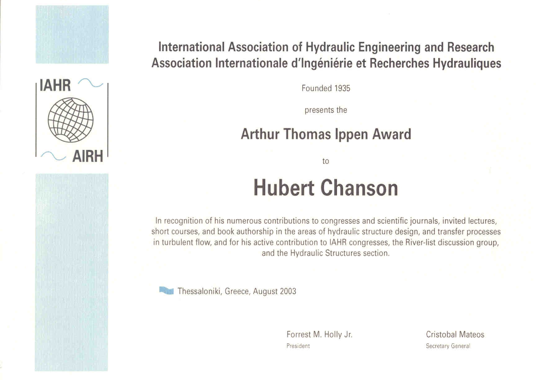
13th IAHR Arthur Ippen awardee - 2004
ASCE-EWRI award for best Practice Paper
Last updated on 6/8/2018
PHOTOGRAPHS
Hydraulic
structures
Historical/heritage
structures
Roman
waterworks
Contemporary
hydraulic structures
Culverts new material
Stepped
spillways and chutes
Check
dams and debris dams
Dam
break
wave and debris flows
Canals / Navigation
Canals
Pipes,
conduits and pipelines
Hydrology & Storms
Floods in Brisbane
and South East Queensland (Australia) on 20-22 May 2009
Floods in
Queensland (Australia) during the summer 2010-2011
Floods in
Queensland (Australia) during Australia's Day in January 2013
Rainstorms
Storms
Rivers and streams of Australia,
Canada, France, Germany,
Japan, Taiwan,
Korea
River
processes
Sediment
transport
in streams
Waterfalls
Flood plains
and Lakes
Artifical
river system, fishway and fish pass
 Coastlines
of Japan, Australia,
France, China,
Italy, Taiwan
Coastlines
of Japan, Australia,
France, China,
Italy, Taiwan
Tidal bores
Whirlpools
Civil Engineering
structures
Atlantic
wall
(Mur de l'Atlantique)
Great
Wall of China
Wind farms
Engineering failures and
accidents of hydraulic and coastal structures
Dams, Extreme reservoir siltation,
Bridges
Earthquake related disasters
Earthquake
engineering
Tsunami
Boxing
Day
26 December 2004 Tsunami disaster / Photographs
of 26 Dec. 2004 tsunami
Taiwan Chi-Chi
earthquake (21 Sept. 1999)
Aircrafts and "Flying Machines"
Cascades, water staircases
and fountains (cascades, fontaines, bassin)
Research experiments
new
material
Lectures
INTERNET RESOURCES
Learn more about ...
(Resources on tidal bore, weir, culvert, spillways, engineering history
...)
Sign the Guestbook
Reprints of Research papers
About Dr Hubert CHANSON
COPYRIGHT & USE OF PHOTOGRAPHS
This gallery of photographs was prepared by Hubert
Chanson. It contains over 900 photographs and there are a wide
variety of images with large gaps in this collection. The photographs were
taken primarily for use in Hubert Chanson's
teaching in order to supplement commercial material. Since not
everyone has the latest browser version, this site has been kept simple
for easy access by the majority. There are too many slow and ugly sites on
the Web produced by people with no expertise in graphic design. Since
Hubert Chanson lacks such expertise himself, he has kept the layout
simple.
The images are JPEG format to keep the size of site
reasonable. With Netscape, make
sure that the JPEG file format is handled by Netscape
Navigator (Edit/Preferences/Navigator/Applications). After viewing each
photograph, click on the button BACK to return to the photograph list
(i.e. this document).
If you or your students find this Web site useful, or
if you have some photographs relevant to this site, you can send Hubert
Chanson a picture postcard.
Copyright
and
Use of Photographs

This work is licensed under a Creative
Commons Attribution-NonCommercial 3.0 Unported License.
You may use these images for no
commercial use only. However the copyright remains attached
to the photograph author(s) {Dr Chanson unless mentioned}
Hydraulic
structures
Historical/heritage
structures
BC 1,300- Arkananian stepped
weir (Greece BC 1,300) : the world's oldest stepped spillway
(Courtesy of Professor KNAUSS). Note the watermill on the foreground and
the new concrete road in the background [Ref.: CHANSON 1997, ANCOLD
Bulletin No. 106]
BC 100- Nabataean dam at Mamshit (Israel, around BC
100). Also called Kurnub dam. Photo No. 1
: the dam across the valley on 10 May 2001 (Courtesy of Dennis MURPHY). Photo No. 2 : deatil of the downstream
wall face on 10 May 2001 (Courtesy of Dennis MURPHY).
AD 1150- Storm waterway at Miya-jima (Japan) - Photo
No. 1 : storm waterway below below Senjò-kaku wooden hall on 19 Nov.
2001. The stepped chute is steep (slope > 45 deg., h ~ 0.4 m). The
Senjò-kaku wooden hall was built by Kyomori (AD 1168) and left unfinished
at his death. It is likely that the waterway design dates from the 12th
century.
AD 1650- Khaju bridge weir,
Iran in 1997 (Courtesy of Dr Zarrati), built in AD 1650 during the Safavid
era in Persia (123-m long, 24 arches). (Dam name also spelled Khadju or
Khadjoo.)
AD 1831- Jones
Falls dam (Canada, 1831). Designed by Colonel John BY, and built
betweeen 1828 and 1831, the 18.7 m high masonry arch dam is used to feed
the Rideau Canal linking Kingston to Ottawa. Photo
No. 1 : View from the left bank (Courtesy of Ken WATSON). More about Arch dams ...
AD 1834- Tillot dam
(France 1834), built as a feeder of the Canal de Bourgogne. It is equipped
with a stepped spillway (design flow rate : 19 m3/s) with converging
sidewalls. View from upstream in January 1997. More about Stepped
spillway
design ...
AD 1854- Zola dam,
(Aix-en-Pr., France 1854) in June 1998 - Arch dam designed by Maurice ZOLA
(1795-1847), father of the novelist Emile ZOLA [Ref.: CHANSON and JAMES
1998, Research Rep. CE157] More about Arch
dams ...
AD 1857- Yan Yean dam (Melbourne VIC, Australia
1857). Australia's first large dam is still in use. Photo
No. 1 : view from the left bank on 1 Feb. 2000.
AD 1870- Malmsbury dam
spillway (Bendigo VIC, Australia 1870). The Eastern (right) spillway
was Australia's first large stepped spillway. It is still in use. [Ref.:
CHANSON 1997, ANCOLD Bulletin No.106 ] More about Stepped
spillway
design ...
AD 1873- Lower Stony Creek
dam (Geelong VIC, Australia 1873). Designed by George GORDON and
built under the supervision of Edward DOBSON, the curved gravity structure
is Australia's first mass concrete dam. It is still in use today. [Ref.:
CHANSON and JAMES, Research Report CE 157] See listing in Structurae.
AD 1880- 75 Miles dam (Warwick QLD, Australia 1880),
the world's oldest concrete arch dam. Photo
No. 1 : the 1880 arch dam shortly before completion (Courtesy of the
MACCROSSAN family) - Photo No. 2 :
details of buttress added in 1901 during the dam heightening (photograph
taken in Jan. 1998). More about Arch dams
... See listing in Structurae.
AD 1882- Le Pont dam
(France 1882). Dam and spillway designed by H. BAZIN. Stepped spillway
with circular step crests and pooled steps. Photograph taken in June 1998.
More about Stepped
spillway
design ...
AD 1890- Gold Creek dam spillway (Australia 1890).
The Gold Creek dam spillway is the world's first concrete stepped
spillway. It was built in non-reinforced concrete and it is still in use
(CHANSON & WHITMORE 1998, Can J Civ Eng). The spillway crest
was refurbished a number of times but the original stepped chute is
intact. The dam is located in Brookfield, Brisbane QLD. Gold Creek dam
stepped spillway in operation in May 1996 : View
from downstream, view from left
bank, view from right bank bottom.
Overflow in May 1996 - View from left
bank. Field trip with students on 9
Sept. 1998. Field trip with students
in Aug. 2000. Student field trip on 11 Sept. 2002 : Photo
1 and Photo 2. Student field trip on 22
September 2006: Photo No. 1 : Gold
Creek reservoir on 25 Sept. 2006; note the low water reservoir level. Photo No. 2 : Intake tower on 22 Sept.
2006; the intake tower was built in 1905, to replace the original
cast-iron tower which failed in 1904. Photo
No.
3 : Concrete stepped chute on 22 Sept. 2006. Photo
No. 4 : Gold Creek flood plain downstream of the Gold Creek dam om
25 Sept. 2006; note the house in the background sitting on inundable land
: flow plain mismanagement ?. Photo No. 5
: House in the flood plain on 25 Sept. 2006. Gold
Creek dam spillway during CIVL3140 field trip on 5 Sept. 2007 : Photo
1 & Photo 2.
UQ CIVL3140 student field trip on 9 Sept. 2009: students
studying the first two steps; Students
on the lower steps of the staircase spillway.Students
inspecting the broad-crest (Courtesy of Stefan FELDER). Overflow on 2 May 2015 after 162 mm of rainfall in the
catchment on 1 May 2015: Photo
No. 1: View from downstream; Photo
No.
2: View from the left bank.
More about Gold
Creek
dam and its historical stepped spillway ... More about Stepped
spillway design ... See listing in Structurae.
AD 1891- Goulburn weir (Victoria, Australia 1891). Photo No. 1 : weir overflow prior to the
gate refurbihsment - Photo No. 2 :
View from left bank, with one opened gate (Q=5 m3/s) on 30 Jan. 2000
[Ref.: CHANSON 1995]. More
about Stepped
spillway
design ...
AD1891- La Tâche dam
(France 1891). Unlined rock stepped cascade, photograph taken in Dec.
1994. (Also called Chartrain dam). More about Stepped
spillway
design ...
AD 1894- Redridge timber crib dam - Photo
No. 1 : old timber crib weir upstream of the Redridge
steel dam (Courtesy of Cindy MILLER). Completed in 1894, the dam was
16.1 m thick at base, 8.5 m thick at crest and 15.2 m high. More
about Timber
crib weirs ...
AD 1897- Junction
Reefs dam (Lyndhurst NSW, Austalia, 1897). Built between 1895 and 1897,
completed in 1897, the Junction Reefs dam is a concrete-brick multiple
arch dam (CHANSON and
JAMES 1998). There are 5 arches, with a 8.5-m span each, sitting on
6 buttresses. The dam foundation and the outside walls are made of
concrete. The arches and buttresses are brick works. The reservoir was
built to supply hydropower to the mining company. Four Pelton wheels were
supplied by the dam. The Junction Reefs dam is well-known wroldwide as a
heritage structure of international significance (WEGMANN 1922, SMITH
1970, SCHNITTER 1994). Interstingly the Junction Reefs dam may be
compared with the Tallong dam. The Tallong dam, completed in 1883, is a
brick buttress-slab structure, still in use. Photo
No.
1 : View from the left abutment on 28 Dec. 1997; note the unlined
rick spillway in the foreground. More about
Arch dams ...
AD 1898- Ashfork dam (Flagstaff Ariz., USA 1898)
also known as Steel dam: Photo No. 1 :
view from downstream (Courtesy of Stephanie YARD, USDA) - Photo
No. 2 : detail of the steel structure (Courtesy of Stephanie
YARD, USDA) - Photo No. 3 : connection
steel dam/masonry abutment (Courtesy of Stephanie YARD, USDA). More
about Steel dams ...
AD 1901- Redridge dam - Photo
No. 1 : view from upstream on 15 Dec. 2001 (Courtesy of Cindy
MILLER). Photo No. 2 : view from
upstream on 15 Dec. 2001 (Courtesy of Cindy MILLER). More about Steel
dams ...
AD 1902- Upper Cordeaux No.
1 dam (Wollongong NSW, Australia 1902) on 25 Nov. 1999 - View from
right bank [Ref.: CHANSON and JAMES 1998) Research Rep. CE157]. More about
Arch dams ...
AD 1903- Upper Coliban dam (Bendigo VIC, Australia
1903). Photo No. 1 : the stepped
cascade at the downstream end of the spillway on 30 Jan. 2000. More about
Stepped
spillway design ...
AD 1905 - Urft
dam (Germany). Photo
No.
1: general view of the dam and spillway on 22 Feb. 2013. Photo No. 2: detail of the spillway
non-linear crest on 22 Feb. 2013. Photo
No. 3 : stepped spillway on 22 Feb. 2013.
AD 1908- De Burgh dam (NSW, Australia). Photo
No. 1 : overflow over the fully-silted dam on 22 July 1998 (Courtesy
pf D.P. James). Photo No. 2 :
overflow on 22 July 1998 (Courtesy of D.P. JAMES). Completed in 1908, the
De Burgh dam was named after its designer Ernst de BURGH. It was built as
a water supply for the narrow-gauge railway line connecting Goondah
NSW to the construction site of the Burrinjuck dam. The De Burgh dam is
Australia's first reinforced concrete arch dam. More about Arch
dams ... More about Extreme
reservoir siltation ...
AD 1911 - Croton Falls dam stepped spillway.
Completed in 1911, the reservoir is part of New York City water supply
system. The stepped spillway is 213 m wide (h = 0.61 m) and it is equipped
with rounded steps (CHANSON 1995,
p. 31, 39 &202). Photo No.1 and No. 2: Overflow in March 2001 (Courtesy
of Mrs J. HACKER).
AD 1911- Koorawatha weir
(1911) in December 1997 (Courtesy of Mr. and Mrs. CHANSON) [Ref.: CHANSON
(1998), Intl. Jl of Sed. Res.; CHANSON and JAMES 1998, Research Rep.
CE157]. More about Arch dams ... More
about Extreme reservoir siltation ...
AD 1912- Cunningham Creek dam
(Harden NSW, Australia 1912) - Dr Chanson inspecting the dam wall and
spillway in December 1997 (Courtesy of Mr. and Mrs. Chanson) [Ref.:
CHANSON and JAMES 1998, Research Rep. CE157]. More about Arch
dams ... More about Extreme
reservoir siltation ...
AD 1915- Fountaindale Creek
dam (Kiama NSW, Australia 1915) on 25 Nov. 1999. More about Arch
dams ...
AD 1916- Ancient sabo works
near Matsumoto, Nagano Prefecture (1895-1920). Artificial
stepped channel designed by a Japanese engineer, modeled on Durance
catchment works (construction : 1916-18). Photograph taken in Nov. 1998.
AD 1917- Korrumbyn Creek dam (Murwillumbah NSW,
Australia). Photo No. 1 : View from
downstream on 25 April 1997. Photo No. 2
: downstream view of the pipeline intake in April 1997. Photo
No. 3 : Korrumbyn Creek downstream of Korrumbyn Creek dam on 18 Aug.
2002. Note the huge bed load material. Photo
No.
4 : Fully-silted reservoir with the dam wall in the background, on
17 Aug. 2002. Photo No. 5 : Bed load
material in the delta (upstream end) of the fully-silted reservoir on 17
Aug. 2002. Photo No. 6 : dam wall
view from the road on 17 Aug. 2002. Before June 2001, the dam wall was not
visible from the road, although the abutment is less than 10 m from the
bitumen. Major floods in May/June 2001 flattened the sub-tropical
rainforest occupying the reservoir. Photo
No. 7 : Mount Warning on 18 Aug. 2002. The climb takes about 4
hours. Photo No. 8 : Korrumbyn Creek,
looking downstrream during student field trip on 4 Sept. 2002. Photo
No. 9 : Korrumbyn Creek dam during student field trip on 4 Sept.
2002. Photo No. 10 : Korrumbyn Creek
reservoir, looking upstream during student field trip on 4 Sept. 2002
Read the history of the dam: download
PDF file. More about Extreme
reservoir siltation ...
AD 1922- Lahontan dam stepped spillway (Nevada, USA
1922). Photo No. 1 : left spillway
overflow on 31 May 1922 (Courtesy of US Bureau of Reclamation and Roy
WINGATE). The left spillway consists of a series of 6 steps (h = 3.05 m, q = 26.6 deg., W = 76.3 m), a converging flat chute
section and a curved stepped channel (3 steps, h = 3.05 m, l = 6.096 m, W
= 45.72 m) with a curvature radius ranging from 39 to 50 m. Note the
training walls. Photo No. 2 : aerial
view of the dam and spillway in 1972 (Courtesy of US Bureau of Reclamation
and Brit STOREY). More about Stepped
spillway
design ...
 Roman waterworks
Read more about the Hydraulics
of Roman aqueducts ...
R1- Pont du Gard, Nîmes
aqueduct, France in June 1998 - View from the right bank
R2- Gier aqueduct (Lyon, France)
Le
Mornantay (Mornant) in June 1998
Chaponost
in June 1998 : looking at the arcades from the head tank of the Beaunant
siphon (i.e. looking toward the upstream)
R3- Les Peirou dam
(France 1891) in June 1998 - The present dam was built on the foundation
of the Roman arch dam at Glanum [Ref.: CHANSON and JAMES 1998, Research
Rep. CE157]. More about Arch dam history
...
R6 - Brévenne aqueduct (Lyon France)
Biternay
in Sept. 2000, inside view looking upstream
R7- Nîmes aqueduct, France. Pont
de Bordnègre in Sept. 2000 : inlet view, showing the bridge pier
shaped to cut the waters. Culvert
beneath the aqueduct between Combe de Sartanette and Combe Saint Joseph,
downstream of Pont du Gard. Main culvert cell (0.8-m wide).
Read : "Hydraulics of a Large Culvert beneath the Roman
Aqueduct of Nîmes." Jl of Irrigation and Drainage
Engrg., ASCE, 2002, Vol. 128, No. 5, pp. 326-330 (Download PDF File).
R8- Fréjus aqueduct (France). Photo
No. 1 : arches de Sainte Croix; Photo
No. 2 : looking upstream; Photo
No. 3 : looking dowsntream (14 Sept. 2000).
R9- Roman aqueduct at Pont-du-Gard,
France in June 1998
Roman dropshaft ('puit de rupture')
rd1- Roman dropshaft in operation : Recret model (Aug.
1998) [Ref.: CHANSON 2000, Am Jl
Archaeology, CHANSON 2002, Jl of
Hyd. Res.]
Regime
R1 : the usual operation mode in Roman aqueduct (photo dc/h
= 0.06)
Regime
R2 : high risks of erosion and damage at the intake of downstream
conduit (photo dc/h = 0.12)
Regime
R3 : at large flow rates, usual operation in modern sewer
dropshaft (photo dc/h = 0.22)
rd2- Roman dropshaft in operation : Valdepuentes
model (90-degree angled outlet) (Aug. 1999) [Ref.: CHANSON
2000, Am Jl Archaeology, CHANSON
2002, Jl of Hyd. Res.]
rd3- Full scale hydraulic model of Roman dropshaft. Drop
in invert elevation: 1.7 m, pool depth: 1 m, shaft dimensions: 0.75 m by
0.76 m, flow rates: 5 to 70 L/s. (Ref.: CHANSON
2004, Jl Irrigation & Drainage Engrg.)
Regime
R1 : photograph for Q = 7.6 L/s (July 2002)
Regime
R3 : photograph for Q = 67 L/s (Aug. 2002)

Contemporary
hydraulic structures
m1- Monteynard dam,
(Drac river, France 1962) in June 1998 - Single-radius concrete arch (H
= 155 m) built on the site of the fully-silted Avignonnet dam [Ref.:
CHANSON and JAMES 1998, Research Rep. CE157]. More about Arch
dams ..
m2- Split Rock dam
spillway, (Tamworth NSW, Australia 1987) on 6 September 1998 -
Flow from bottom to top (Courtesy of Mr. Noel BEDFORD)
m3- Benmore dam spillway (New Zealand). Photo
No. 1 : view from dowsntream, "It's hard to believe from this
photograph that the spillway was half a kilometer long." (Courtesy of
Bill REA) - Photo No. 2 : flip
bucket peration at 2,700 m3/s (Courtesy of Bill REA).
m4- Rubber dams
Bedford weir
(Qld, Australia) : 195-m long 1.45-m high rubber dam installed in 1997.
Photo No. 1 : inspection of the
inflated dam with deflector in 1997 (Courtesy of Queensland Rubber
Company); Photo No. 2 : overflow of
the inflated rubber dam in 1998(Courtesy of Queensland Rubber Company).
Tucombil weir (Nsw, Australia) : 61-m long, 1.8-m high water filled
rubber dam installed in the 1980s and dimantled in the early 2000s. The weir was built on the Tucombil
canal to prevent tidal effects (i.e. salt intrusion) between the
Richmond river and the Evans river systems. During large flood events,
the weir was to be deflated to reduce flooding effects in the Rcihmond
river catchment.
First rubber dam
built by Queensland Rubber Company; Photo
No. 3 : fully-inflated weir on 2 Nov. 1997. More about Rubber
dam hydraulics ...
m5- Chinchilla weir
(Chinchilla QLD, Australia 1973). Photograph taken on 8 Nov. 1997 during
low overflow. Minimum Energy Loss weir designed with the asistance of
Professor Gordon McKAY. Weir height: 14 m, Crest length: 410m, Spillway
capacity: 850 m3/s, Condamine river. More information : CHANSON,
Butterworth-Heinemann, 1999, pp. 417-421 & 316. More about Minimum Energy Loss weirs ...
m6- Lemontree weir
(Cecil Plains QLD, Australia 1979). Photograph taken on 8 Nov. 1997.
Minimum Energy Loss weir design on the Condamine river. More information
: CHANSON, Butterworth-Heinemann, 1999,
pp. 417-421. More about Minimum Energy Loss
weirs ...
m8- Dam spillways in Mexico : El
Mahone or Miguel Hidalgo in Sinaloa state; Ticuitaco,
Michoacán (From "Grandes Presas de México", C.N.A., courtesy of Mr V.H.
Alcocer Yamanaka).
m9- Baffed chute
dissipation structure immediatly off the beach, under bicycle path
bridge on Irago Peninsula, Japan (27 Mar. 1999).
m10- Shasta dam (Redding, California, USA 1945).
183-m high curved gravity dam (more technical
details). Photo No. 1 :
General view of spillway with roll waves in Aug. 1999 (Courtesy of
Daniel STEPHENS) - Photo No. 2 :
Details of roll waves (Courtesy of Daniel STEPHENS) - Photo
No. 3 : view from the crest looking at the plunge pool (Courtesy
of Daniel STEPHENS).
m11- Surfing a hydraulic jump roller in the English
Garden, Munich (Germany) - Photo No. 1
: a surfer departing from the left bank (Courtesy of Dale YOUNG). Photo
No. 2 : looking downstream at a surfer (Courtesy of Dale YOUNG).
m12- Clyde dam spillway (NZ). Photo
No. 1 : spillway during construction in March 1988. Note the
scaffolding in the spillway aeration device. More about spillway
aeration devices ...
m13- Foz Do Areia dam spillway (Brazil). H = 160
m, spillway slope: 14.5 deg. slope, design discharge: 11,000 m3/s, chute
length: 400 m. Photo No. 1 : spillway
in operation (flow from bottom to top), note the spillway aeration
devices (Courtesy of Prof. N. PINTO). More about spillway
aeration devices ...
m14- Itaipu dam spillway (Brazil/Paraguay). H =
196 m, Parana river, completed in 1982, Spillway slope: 10 deg., W=345
m, design discharge: 61,400 m3/s, equipped with 2 air slots. Photo
No. 1 : spillway in operation (flow from bottom to top), note the
air duct intakes on the left wall (Courtesy of Prof. N. PINTO). Photo
No. 2 : Spillway in operation (Courtesy of Itaipu Binacional). Photo No. 3 : Flip bucket (Courtesy
of Itaipu Binacional). More on Itaipu
dam ...
More about spillway aeration devices ...
m16- Drop structure (weir) operation in Japan. The
small drop structure is located on the Futu-gawa river, Toyohashi, Japan
about 500 m upstream of a major shopping center. Photo
No. 1 : operation durng dry period on 23 Jan. 1999. Photo
No. 2 : small overflow after 50-100 mm of rain during the past 24
hours, on 11 April 1999. Photo No. 3
: medium overflow in May 1999 after 150 mm of rainfall in the last 24
hours.
m16- Trigomil dam (Mexico). RCC dam: H = 61 m.
Spillway: 51-degree slope, 75-m wide chute. Photo
No. 1 : dam spillway in March 2002, note the spillway aeration
device (Courtesy of Víctor Hugo Alcocer Yamanaka). Photo
No. 2 : upstream face of the dam and spillway intake in March 2002
(Courtesy of Víctor Hugo Alcocer Yamanaka).
m17- Hinze dam (Gold Coast Qld, Australia). Photo
No. 1 : spillway ogee crest during CIVL4120 student field trip on
4 Sept. 2002. Photo No. 2 : turning
vanes at the downstream end of the steep chute, during CIVL4120 student
field trip on 4 Sept. 2002. Hinze dam spillway
(Stage 3) in operation on 29/1/2013 at 12:15, Q ~ 170 m3/s. Photo No. 3: View from downstream
of the stepped spillway operation. Photo
No. 4: View from upstream of the uncontrolled ogee and stepped
chute operation. See also: "Interactions between a Developing Boundary
Layer and the Free-Surface on a Stepped Spillway: Hinze Dam Spillway
Operation in January 2013", Proc. 8th
International Conference on Multiphase Flow ICMF 2013, Jeju,
Korea, 26-31 May, Gallery Session ICMF2013-005 (Video duration: 2:15). (Description)
(Record
at
UQeSpace) (Video
movie at UQeSpace).
Site visit with CIVL4120 Advanced hydraulics students on 24 October
2014: Photo No.11:
general
view of stepped spillway and stilling basin. Photo
No. 12: stilling basin and turning veins leading to an ogee weir.
Photo No. 13:
stepped spillway with 3.3 m high baffle blocks in the foreground. Photo No. 14: details of baffle
block. Photo No. 15:
engineering students discussing about the spillway system next to a
baffle block. Photo
No. 16: CIVL4120 students with Professor Chanson at the spillway
toe. Photo No. 17:
stepped spillway toe and stilling basin. Small
overflow on 3 May 2015: Photo
No. 18: View from downstream; Photo
No. 19: View from upstream, with flow direction from top to
bottom.
m19- Swanbank Minimum Energy Loss spillway
(Ipswich Qld, Australia 1965). Photo No.
1 : spillway inlet, view from the dam wall on 6 Sept. 2002. Photo
No. 2 : spillway ogee, with the power station in background on 6
Sept. 2002. More about Minimum Energy Loss
weirs ... More about Swanbank
power plant.
m20- Sandy Creek at Clermont QLD (Australia 1963).
Photo No. 1 : Early stages of
construction in 1962 (Courtesy of Mr Keith JAMES). Photo
No. 2 : Downstream face near completion in early 1963 (Courtesy of
Mr Keith JAMES). Photo No. 3 :
Workers on the downstream face near completion in 1963 (Courtesy of Mr
Keith JAMES). Photo No. 4 : view
from the right bank on 3 Sept. 2002 (Courtesy of Mr Keith JAMES). Photo
No. 5 : detail of the crest intake on 3 Sept. 2002 (Courtesy of Mr
Keith JAMES). Photo No. 6 : Flood
overflow on 8 March 1993 (Courtesy of Mr A.J. HOLMES). Photo
No. 7 : Flood overflow in Feb. 1999 (Courtesy of Mr A.J.
HOLMES). More information : CHANSON,
Butterworth-Heinemann, 1999, pp. 417-421. More about Minimum
Energy Loss weirs ...
m21- Pertusillo
dam (Italy, 1961). Arched gravity
concrete dam: stability by a combination of gravity and arch . Arch
opening angle : 116 deg., H = 95 m, L = 270 m, e =
3.50 m, E = 42 m. Catchment : 530 km2. Reservoir capacity : 155 Mm3. River
Fiume Agri. Purpose : flood control, hydropower and drinking water supply
(for Tarento, Bari ...). Spillway system: tunnel spillway on left bank. Photo No. 1 : view fron the right bank
on 17 Feb. 2004. Photo No. 2 : scale
model of the dam and valley, looking upstream; note mid-level outlet chute
and ski jump on lef tof photograph. Photo
No. 3: scale model of the dam, looking downstream; note spillway
intake on left of photograph, on the left abutment. Photo
No. 4 : mid-level outlet steep chute and ski jump, looking
downstream on 17 Feb. 2004.
m22- Three Gorges Project and
Dam (Yichang, China, 2002-2007). Concrete gravity dam. Length:
2300 m, Height: 181 m. Powerplant: 32 Francis turbines (700 MW each). Photo No. 1 : Overall view of the scale
model of the project on 20 Oct. 2004, looking from the right bank; the dam
wall is in white. Photo No. 2 : Dam
wall viewed from the left abutment on 20 Oct. 2004. Photo
No. 3 : Construction of the third section on 20 Oct. 2004; view from
the dam crest above the spillway section, looking towards the right
abutment. Photo No. 4 :
Navigation lock on 20 Oct. 2004; the navigation lock is a two-way
system, with 5 locks each; each lock is 280 m long and 34 m wide. Photo
No. 5 : Three Gorges Reservoir on 20 Oct. 2004, looking from
the right bank at a hydrofoil passenger ship. Photo
No. 6: scour outlet discharge below the spillway section on 20 Oct.
2004 (Q = 7000 m3/s, V = 35 m/s). Photo No.
7 : high-velocity flow from an outlet sluice on 20 Oct. 2004 (V = 35
m/s); note the large amount of 'white waters' highlighting strong
free-surface aeration. Photo No. 8 :
free-surface aeration along the bottom outlet jet flow downstream of the
spillway section on 20 Oct. 2004 (V = 35 m/s). Photo
No. 9: scale model of a 700 MW Francis turbine on 20 Oct. 2004.
m23- Barrier mitigation
structure, Toronto, Ontario, Canada on the East Don River (2005).
Trapezoidal drop structure and downstream rock chute ramp built in 2005 on
the East Don river, Toronto, Ontario, Canada by the Toronto and Region
Conservation Authority. The barrier is a concrete drop structure at the
upstream end of a trapezoidal concrete channel. The original
objective of our project was to simply provide improved fish access over
the drop structure using a rocky ramp structure. Coast Guard regulations
stipulated that their approvals on the design would require that a portage
be included in the works for canoists and kayakers around this drop
structure. As a conservation authority mandated to promote public
safety around waterways. As a compromise, a downstrean rocky ramp
allows for canoe/kayak access over the drop structure, as well as provide
fish access upstream. A notch was cut in the centre of the concrete drop
structureto concentrate the baseflow and provide sufficient depth for a
canoe or kayak to flow over the drop structure. At very low flow
conditions, it is simple for the canoists to walk their canoes down the
centre of the ramp.
Photo No. 1 : structure on 19 Aug. 2005
after completion, taken just afew hours before a flood exceeding a 1:100
year event hit this section of the river, viewed from the right bank (Coutesy of the Toronto and Region Conservation Authority 2005
and Kenneth DION). The structure largely remained intact during the flood
event with only minor shifting of the materials. Photo
No. 2 : massive damage in the downstream trapezoidal channel after
the 1:100 flood event (Coutesy
of the Toronto and Region Conservation Authority 2005 and Kenneth DION).
m24- Chungju dam, Korea.
Completed in 1985, the concrete gravity dam is 97.5 m high, 447 m long and
it is equipped with 4 100-MW turbines. Located on the South Han river, the
reservoir is multipurpose: flood control, hydropower and water supply. Photo No. 1 : Chungju dam on 14 Sept.
2005. Photo No. 2 : details of the
Chungju dam spillway on 14 Sept. 2005. Photo
No. 3 : Details of the spillway aeration devices; the second bottom
slot is unnecessary. Photo No. 4 :
Detail of the first aeration slot. More about Spillway aeration devices ....
m25- Chechen river dam,
Pingtun county, Taiwan. Main water supply for the Pingtung county.
Rockfill dam. Smooth chute spillway with ski jump and artificial plunge
pool. Photo No. 1 : view from
downstream on 21 Nov. 2006. Photo No. 2
: details of the spillway system on 21 Nov. 2006.
m26- North
Pine
dam, Brisbane QLD (Australia). North Pine dam is a 40 m high
concrete gravity dam; it is the main water suppy for the North of
Brisbane. Spillway in operation on 22 May 2009
morning. Photo
No.
1: spillway overflow at 07:35. Photo
No.2: details of the free-surface aeration on the chute.
m27- Lake
Kurwongbah
dam (also called Sideling Creek dam). The dam is equipped with a
Minimum Energy Loss spillway intake. Spilway operation on 22 May 2009 morning.
Photo No.1: spillway intake with a
very small overflow at 08:20. Photo No. 2:
flip bucket operation; note the discharge confined to the low flow
section. Spillway in operation on 29/1/2013 at
10:00. Photo No. 1:
Minimum Energy Loss (MEL) inlet operation. Photo
No. 2: Flip bucket and tailrace channel.
m28 - Somerset
dam and spillway in operation on 28/1/2013 at 10:30 - Gates
fully-opened (Q ~ 450 m3/s).
More about Free
surface aeration in hydraulic structures ...
Water
treatment plants
wtt1- Molendinar Water Purification Plant (Gold
Coast Qld, Australia). Photo No. 1 :
plant operation during CIVL4120 student field trip on 4 Sept. 2002.
wtt2- Pertusillo
drinking
water treatment plant (Italy). Photo
No. 1 : Riser in operation on 17 Feb. 2004. Photo
No. 2 : Dry riser on 17 Feb. 2004. Photo
No. 3 : Ventury system at the outflow of the treatment plant on 17
Feb. 2004.
Culverts
cv1- Standard culverts
Photo
No. 1 : outlet of a circular pipe culvert along Gap Creek Rd, The
Gap, Brisbane Australia. Photo No. 2
: culvert inlet operation in St Lucia next to the golf course (flow from
right to left) on 31 Dec. 2001. Photo
No. 3 : physical model of box culvert in operation at design
flow rate (flow from bottom to top). Photo
No.
4 : box culvert at Oxenford on 18-09-2003. Reference : CHANSON
(1999), "The Hydraulics of Open Channel
Flow: an Introduction", Butterworth-Heinemann; Subject CIVL3140 Catchment hydraulics.
Photo
No. 11: culvert outlet along Whitton Creek on 30 March 2017.
Photo
No. 21: culvert inlet along Caswell Creek on 31 March 2017.
Minimum energy loss (MEL)
culverts and waterways
cv10- Structure No. 01 : MEL culvert No. MEL-C-2 (CHANSON
1999). Design discharge : 220 m3/s. Located along Norman Creek
underneath SE Freeway parallel to Birdwood St, Brisbane (Australia). Inlet, looking from the left bank on
13 May 2002.
cv11- Structure No. 02 : MEL
culvert No. MEL-C-3 (CHANSON 1999).
Design discharge : 220 m3/s, 7 cells of 2-m width each. Located along
Norman Creek underneath Ridge St, Brisbane (Australia). Inlet, looking
from the right bank. Note the handrail alongthe bicycle/footpath passing
in one cell. Field trip with
students in Aug. 2000. Culvert outlet
during field trip with students in Aug. 2001 (Courtesy of Mr A.K.
ABDULLAH SANI). Outlet viewed from
downstream on 13 May 2002 (Courtesy of C. HINTON). Inlet
operation and Outlet operation
on 31 Dec. 2001 after a rainstorm (Q ~ 60-70 m3/s). Approach
flood
plain during field work on 13 May 2002, note the outlet of the
MEL-W-1 waterway in the background. Inlet
during survey on 13 May 2002. Downstream
flood plain on 13 May 2002. Outlet during
CIVL3140 field trip on 18-09-2003: Photo
No.1, Photo No. 2, Photo No. 3. Operation on 7 Nov. 2004: flood flow
(80-100 m3/s) after 60-150 mm of rainfall in less than 3 hours: Photo
No. A1: outlet of the Ridge St MEL culvert (MEL-C-3) on 7 Nov.
2004, looking upstream; Photo No. A2:
inlet operation, looking downstream; Photo
No. A3: inlet operation, looking upstream from the culvert
embanment; note the MEL waterway No. MEL-W-1 in background. Outlet during CIVL3140 field trip on 5 Sept. 2007 : Photo
1 & Photo 2. Culvert
operation during the floods on 20 May 2009: Photo
No.1: inlet operation around 09:10. Photo
No.2: inlet operation at 11:00; note the larger flow rate through
the culvert and the hydraulic jump roller in the foreground.
CIVL3140 student field trip on 9 Sept. 2009: students
walking in the outlet with the low-flow drain in the
foreground.
More about Minimum
Energy
Loss (MEL) Culverts and bridge waterways ...
cv12- Structure No. 03 : MEL
waterway No. MEL-W-1 (CHANSON 1999). Design discharge : 200 m3/s,
barrel width : 10 m. Located on Norman Creek underneath the S-E freeway
beneath Ridge St. Looking upstream at the outlet and barrel. Outlet
operation (view from downstream) on 31 Dec. 2001 after a rainstorm
(Q ~ 60-70 m3/s). Field trip by
CIVL4510 students (where are they?) on 13 May 2002. Operation on 7
November 2004 : flood flow (80-100 m3/s) after 60-150 mm of rainfall in
less than 3 hour: Photo No. a1: MEL
water MEL-W-1 barrel in operation on 7 Nov. 2004, looking downstream;
note the standing wave flow; Photo No.
a2: inlet operation, view from right bank; Photo
No. a3: outlet operation, looking upstream.
CIVL3140 student field trip on 9 Sept. 2009: student
group in front of the inlet.
More about Minimum
Energy Loss (MEL) Culverts and bridge waterways ...
cv13- Structure No. 04 : MEL
culvert No. MEL-C-6 (CHANSON 1999).
Design discharge : 36 m3/s, Barrel width : 5.5 m, Barrel length : 137 m,
Invert drop : 1.2 m. MEL culvert at Redcliffe (Australia) between the
shopping center and the sea. View of the outlet looking at the Moreton
Bay. More about Minimum
Energy Loss (MEL) Culverts and bridge waterways ...
cv14- MEL culvert No. MEL-C-4 (CHANSON
1999). Design discharge : ~220 m3/s. MEL culvert beneath the
Gateway motorway (Brisbane, Australia). Photo
No. 1 : inlet on 11 Sept. 2002 during CIVL3140 student field trip.
Photo No. 2 : inlet wingwall on 11
Sept. 2002 during CIVL3140 student field trip.
More about Minimum Energy Loss (MEL)
Culverts and bridge waterways ...
cv15- MEL culvert No. MEL-C-5 (CHANSON
1999). Design discharge : ~100 m3/s. MEL culvert beneath the
Gateway motorway (Brisbane, Australia). Photo
No. 1 : inlet on 11 Sept. 2002 during CIVL3140 student field trip.
Photo No. 2 : students in inlet
channel on 11 Sept. 2002 during CIVL3140 student field trip. Photo
No. 3 : students at the dowsntream end of the barrel on 11 Sept.
2002 during CIVL3140 student field trip. More about Minimum Energy Loss (MEL) Culverts and bridge
waterways ...
cv21 - Structure No. 05 : MEL culvert No. MEL-C-X2,
Ekibin Park, on Norman Creek. Design discharge : 220 m3/s. Built in
1971. Located underneath South-East Freeway. Inlet
survey during Field survey CIVL4510 on Mon 13 May 2002. Inlet
during CIVL3140 field trip on 18-09-2003. CIVL3140 student field
trip on 9 Sept. 2009: Inlet
of the MEL culvert, looking upstream; Outlet
of of the MEl culvert.
cv22 - Structure No. 06 : MEL culvert No. MEL-C-X1 (CHANSON
1999), Cornwall St, on Norman Creek. Upstream
flood plain on 13 May 2002. Inlet
survey during field survey CIVL4510 on Mon. 13 May 2002. Outlet operation on 30 March 2017.
More
about Minimum Energy Loss (MEL) Culverts and
bridge waterways ... Bibliographic
references : APELT (1983), CHANSON
(1999), CHANSON
(2000), CHANSON (2001)
 Stepped spillways and chutes
Historical stepped spillways
BC 1,300- Arkananian stepped
weir (Greece BC 1,300) : the world's oldest stepped spillway
(Courtesy of Professor KNAUSS). Note the watermill on the foreground and
the new concrete road in the background [Ref.: CHANSON 1997, ANCOLD
Bulletin No. 106]
AD 1150- Storm waterway at Miya-jima (Japan) - Photo
No. 1 : storm waterway below below Senjò-kaku wooden hall on 19 Nov.
2001. The stepped chute is steep (slope > 45 deg., h ~ 0.4 m). The
Senjò-kaku wooden hall was built by Kyomori (AD 1168) and left unfinished
at his death. It is likely that the waterway design dates from the 12th
century.
AD 1650- Khaju bridge weir,
Iran in 1997 (Courtesy of Dr Zarrati), built in AD 1650 during the Safavid
era in Persia (123-m long, 24 arches). (Dam name also spelled Khadju or
Khadjoo.)
AD 1834- Tillot dam
(France 1834), built as a feeder of the Canal de Bourgogne. It is equipped
with a stepped spillway (design flow rate : 19 m3/s) with converging
sidewalls. View from upstream in January 1997.
AD 1870- Malmsbury dam
spillway (Bendigo VIC, Australia 1870). The Eastern (right) spillway
was Australia's first large stepped spillway. It is still in use. [Ref.:
CHANSON 1997, ANCOLD Bulletin No.106 ] More about Stepped
spillway
design ...
AD 1882- Le Pont dam
(France 1882). Dam and spillway designed by H. BAZIN. Stepped spillway
with circular step crests and pooled steps. Photograph taken in June 1998.
More about Stepped
spillway
design ...
AD 1890- Gold Creek dam spillway (Australia 1890).
The Gold Creek dam spillway is the world's first concrete stepped
spillway. It was built in non-reinforced concrete and it is still in use
(CHANSON & WHITMORE 1998, Can J Civ Eng). The spillway crest
was refurbished a number of times but the original stepped chute is
intact. The dam is located in Brookfield, Brisbane QLD. Gold Creek dam
stepped spillway in operation in May 1996 : View
from downstream, view from left
bank, view from right bank bottom.
Overflow in May 1996 - View from left
bank. Field trip with students on 9
Sept. 1998. Field trip with students
in Aug. 2000. Overflow on 2 May 2015 after 162 mm of rainfall in the
catchment on 1 May 2015: Photo
No. 1: View from downstream; Photo
No. 2: View from the left bank.. More about Gold
Creek dam and its historical stepped spillway ... See listing
in Structurae.
AD 1891- Goulburn weir (Victoria, Australia 1891). Photo No. 1 : weir overflow prior to the
gate refurbihsment - Photo No. 2 :
View from left bank, with one opened gate (Q=5 m3/s) on 30 Jan. 2000
[Ref.: CHANSON 1995]. More
about Stepped
spillway
design ...
AD1891- La Tâche dam
(France 1891). Unlined rock stepped cascade, photograph taken in Dec.
1994. (Also called Chartrain dam). More about Stepped
spillway
design ...
AD1905- New Croton dam stepped spillway (New York
NY, USA 1905). Photo No. 1 : in July
1999 (Courtesy of Mrs J. HACKER) (Ref.: CHANSON
2001, Balkema). Completed in 1905 for the water supply of New York
city, the 90.5-m high dam was the world's tallest dam at the time. It was
equipped with a stepped spillway (capacity: 1550 m3/s). In October 1955,
the spillway was heavily damaged by a water release of about 650 m3/s.
(Ref.: CHANSON 1995, Pergamon,
pp. 189-191). The spillway was subsequently repaired and it is still used.
The stepped cascade appeared in the movie "Daylight" (1996), starring
Sylvester Stallone.
AD 1905 - Urft
dam (Germany). The 91 m wide chute was cut into the rock and
lines with concrete. The maximum discharge capacity is 220 m3/s. Photo No. 1: general view of the dam
and spillway on 22 Feb. 2013. Photo
No. 2: detail of the spillway non-linear crest on 22 Feb. 2013. Photo No. 3 : stepped
spillway on 22 Feb. 2013.
AD 1911 - Croton Falls dam stepped spillway (USA,
1911)). Completed in 1911, the reservoir is part of New York City water
supply system. The stepped spillway is 213 m wide (h = 0.61 m) and it is
equipped with rounded steps (CHANSON
1995, p. 31, 39 &202). Photo No.1
and No. 2: Overflow in March 2001
(Courtesy of Mrs J. HACKER).
AD 1916- Ancient sabo works
near Matsumoto, Nagano Prefecture (Japan 1895-1920). Artificial
stepped
channel designed by a Japanese engineer, modeled on Durance
catchment works (construction : 1916-18). Photograph taken in Nov. 1998.
AD 1922- Lahontan dam stepped spillway (Nevada, USA
1922). Photo No. 1 : left spillway
overflow on 31 May 1922 (Courtesy of US Bureau of Reclamation and Roy
WINGATE). The left spillway consists of a series of 6 steps (h = 3.05 m, q = 26.6 deg., W = 76.3 m), a converging flat chute
section and a curved stepped channel (3 steps, h = 3.05 m, l = 6.096 m, W
= 45.72 m) with a curvature radius ranging from 39 to 50 m. Note the
training walls. Photo No. 2 : aerial
view of the dam and spillway in 1972 (Courtesy of US Bureau of Reclamation
and Brit STOREY). More about Stepped
spillway
design ...
Modern stepped chute designs
ss1- Joe Sippel weir
(Murgon QLD, Australia) - Completed in 1984, the 6.5-m high stepped weir
is used for irrigation and water regulation purposes. The structure was
built of steel sheet piles and concrete slabs. It is located upstream of
the Silverleaf weir. Photo No. 1: in
November 1997. Photo
No. 2: on 5 March 2013. Photo
No. 3: details of the plunge point on 5 March 2013.
ss2- La Grande 2 spillway (Québec,Canada) -
Unlined rock stepped cascade in operation in 1983: Photo
No. 1, view from downstream (Courtesy of Michel Lefebvre) - Photo
No.
2 : view of the upstream steps (Courtesy of Michel Lefebvre).
ss3 Melton dam overflow stepped spillway (Melton
VIC, Australia 1916). The Melton dam is an earthfill structure.
Completed in 1916, the dam was heightened twice because of the rapid
reservoir siltation. During the last refurbishment in 1994, an overflow
stepped spillway was added. Photo No. 1
: general view (30 Jan. 2000). Photo
No. 2 : details of the dam overflow spillway (30 Jan. 2000). More
about Extreme reservoir siltation
...
ss4- Riou dam (France 1990). RCC stepped spillway
: h = 0.43 m. Photo No. 1 : view
from downstream at sunset (photograph taken in Nov. 1994). Photo
No. 2 : view from right bank (photograph taken in Nov. 1994). Photo No. 3 : view from the right
bank of the crest, chute and stillign basin in June 1998. Photo
No. 4 : view from downstream in June 1998. More
information ...
ss5- Santa Cruz arch dam
stepped spillway (New Mexico, USA). Completed in 1929, the Santa
Cruz dam was a masonry arch dam. In 1987, the dam was reinforced by
concrete buttresses and roller compacted concrete. A new overfflow
stepped spillway was built between two buttresses (Design: 56 m3/s)
(Courtesy of US Bureau of Reclamation and John LABOON). More
information ...
ss6- Jordan II weir
(Gatton QL, Australia 1992). Reinforced-earth stepped overflow weir (H =
5.3 m). Photograph in Feb. 1998.
ss11- Brushes Clough dam spillway (1859-1991).
Overflow embankment spillway system with precast concrete blocks. Photo
No. 1 : General view in 1993 (Courtesy of Mr GARDINER, NWW). Photo
No. 2 : details of the concrete blcoks, showing the drainage holes
(Courtesy of Mr GARDINER). More about Embankment
overflow stepped spillways: earth dam spillways with precast
concrete blocks...
ss12- Zaraysk dam
(also called Laraisky), Russia (Courtesy of Prof. Y. PRAVDIVETS).
Overflow embankment spillway made of precast concrete blocks. More about
Embankment overflow stepped
spillways: earth dam spillways with precast concrete blocks...
ss13- Loyalty Road Flood Retarding dam spillway
(Sydney NSW, Australia, 1996) - Photo
No. 1 : view from the right bank (Courtesy of D.Patrick JAMES). Photo No. 2 : view from downstream
(Courtesy of D.Patrick JAMES). Dam height : 30 m. RCC construction.
Spillway capacity : 1,040 m3/s. Chute width : 30 m.
ss14- Chechen weir,
Pingtung county, Taiwan. Built on the Chechen river about 5 km upstream
of the river mouth, the diversion weir was built for irrigation purposes
with diversion canals on both left and right banks. Also called Chechung
weir. Photo No. 1 : view from the
left bank in Dec. 1998. Photo No. 2
: view from the left bank on 21 Nov. 2006. Photo
No. 3 : view from left bank on 21 Nov. 2006; compare this view
with the Photo
No. 1.
ss18- Bucca weir(Bucca
QLD,
Australia 1987) (H. CHANSON, 23 Dec. 2001). RCC irrigation weir on the
Kolan river.
ss19- Neil Turner weir (Mitchell QLD, Australia
1984). 5.9 m high stepped weir on the Maranoa river. Photo
No. 1 : general view in July 2001 (Courtesy of Chris PROCTOR). Photo No. 2 : detail of steps in July
2001 (Courtesy of Chris PROCTOR).
ss20- Salado 10 embankment dam and
secondary stepped spillway (Courtesy of Craig SAVELA and USDA, Natural Resources Conservation Service; National Design,
Construction and Soil Mechanics Center, Fort Worth, Texas).
ss21- Choctaw
8A
embankment dam and secondary stepped spillway (Courtesy of Craig
SAVELA and USDA, Natural Resources Conservation Service; National
Design, Construction and Soil Mechanics Center, Fort Worth, Texas).
ss22- Robina, Gold
Coast (Australia 1996) - Stepped weirs built along an artifical storm
watercourse around the Robina shopping twon QLD. Photo
No. 1 : Construction of the first weir (weir No. 5) in April
1996. Note the installation of aprecast step over a
coarse-aggregate concrete serving as a drainage layer over the
embankment and the crane is at about the elevation of the weir crest. Photo No. 2 : Small overflow
above the same weir No. 5 on 3 Feb. 2003.
ss23- Les Olivettes dam, Vailhan (France
1987) - RCC dam (36 m high, 254 m long) for flood mitigation (catchment
area: 29.5 km2) - Stepped spillway: h = 0.6 m, ogee crest, W = 40 m,
Qmax = 290 m3/s, energy dissipation: steps + dowsntream plunge pool. Photo No. 1 : view from left bank in
March 2003 (Courtesy of Mr and Mrs CHANSON). Photo No. 2 : view from downstream,
with the counterweir and plunge pool in foreground in March 2003
(Courtesy of Mr and Mrs CHANSON). Photo
No. 3 : view from the left bank in March 2003 (Courtesy of Mr and
Mrs CHANSON).
ss24- Pedrogao dam,
Moura (Portugal, 2006). Completed in March 2006, the Pedrogao dam is a
RCC gravity dam (H = 43 m, L = 473 m) with an uncontrolled overflow
stepped spillway (h = 0.6 m, 1V:0.75H). The dam is equipped also
witha fish lock/lift. The reservoir is located immediately
downstream of the Alqueva dam which is multipurpose reservoir for
irrigation (326 km of open channels, 9 main pump stations)
and hydropower (2 * 130 MW pump-turbines). Photo
No. 1 : view from right bank on 4 Seopt. 2006. Photo
No. 2 : view from left bank on 4 Sept. 2006.
ss25- Hinze
dam spillway (Stage 3). Operation on 29/1/2013 at 12:15,
Q ~ 170 m3/s. Photo
No. 1: View from downstream of the stepped spillway operation. Photo No. 2: View
from upstream of the uncontrolled ogee and stepped chute operation. See also: "Interactions between a Developing Boundary Layer
and the Free-Surface on a Stepped Spillway: Hinze Dam Spillway Operation
in January 2013", Proc. 8th
International Conference on Multiphase Flow ICMF 2013, Jeju,
Korea, 26-31 May, Gallery Session ICMF2013-005 (Video duration: 2:15). (Description)
(Record
at
UQeSpace) (Video
movie at UQeSpace). Site visit with
CIVL4120 Advanced hydraulics students on 24 October 2014: Photo No.11: general view of
stepped spillway and stilling basin. Photo
No. 12: stilling basin and turning veins leading to an ogee weir.
Photo No. 13:
stepped spillway with 3.3 m high baffle blocks in the foreground. Photo No. 14: details of baffle
block. Photo No. 15:
engineering students discussing about the spillway system next to a
baffle block. Photo
No. 16: CIVL4120 students with Professor Chanson at the spillway
toe. Photo No. 17:
stepped spillway toe and stilling basin. Small overflow on 3 May 2015: Photo No. 18: View
from downstream; Photo
No. 19: View from upstream, with flow direction from top to
bottom. Photo No. 20:
Stilling basin with turning vane in the foreground and baffle blocks,
with the the steep stepped spillway in the background on 14 Oct. 2014.
Photo
No. 21: Stepped spillway on 14 Oct. 2014. Photo
No. 22: Stilling basin and baffle block on 14 Oct. 2014.
Photo
No. 23: eastern brown snake in stilling basin
on 14 Oct. 2014.
ss26- Paradise
dam, Biggeden QLD (Australia) - RCC gravity dam equipped
with an uncontrolled stepped spillway. Photo
No. 1: General view of the spillway on 5 March 2013. Photo No. 2: View of the spillway
and stilling basin operation on 5 March 2013. Photo
No. 22: Details of the free-surface next to the inception of
free-surface aeration on the stepped spillway on 5 March 2013. Photo
No.
23: turbulence and air-water flow in the stilling basin on 5
March 2013.
ss30- Stepped road gutter systems : another
application of the stepped chute design. Photo
No. 1 : steep gutter along the Western freeway, Brisbane
(Photograph taken in Dec. 1999). Photo
No. 2 : double road gutter looking downstream, next to Sumner Rd
freeway entrance, between Darra and Mt Ommaney, Brisbane (Photogaph
taken in Nov. 1996).
Read "Energy Dissipation and Air Entrainment
in a Stepped Storm Waterway: an Experimental Study." Jl of Irrigation and Drainage Engrg., ASCE, 2002,
Vol. 128, No. 5, pp. 305-315 (Download PDF
File).
ss40- Artifical stepped cascade at Biloela
(QLD, Australia). Design flow: 390 m3/s, step height: 2 m, width: 100
m. Photo No. 1 : General view
shortly after construction in 2002 (Courtesy of Dr John MACINTOSH). Photo No. 2 : View of a step
arrangement, from the right bank (Courtesy of Dr John MACINTOSH). Photo No. 3 : 1:16 scale
model, based upon a Froude similitude (Courtesy of Dr John MACINTOSH).
Photo No. 4 : physical model in
operation for Q = 10 L/s (20 m3/s prototype); all the water flows as
seepage; the colours are paint sprayed on the rockfill to visualise
erosion and scour. Photo No. 5 :
physical model in operation for Q = 103 L/s (210 m3/s prototype); note
overflows and seepage, and the hydraulic jump downstream of the plunge
point.
ss50- Research on stepped
spillways at the University of Queensland : 22º slope, h = 0.10
m, l = 0.25 m, W = 1 m, q = 0.103 m2/s, dc/h = 1.0. Photo
No. 1 : View from upstream looking towards the inception point
of air entrainment. Photo No. 2:
Side view (Y90 = 0.078 m, Cmean = 0.48, Fmax = 149 Hz at the probe
location) (Photographs taken on 7 July 2000). Photo
No. 3 : dc/h = 1.5 (flow from left to right, run
Q23). Photo No. 4 : dc/h
= 1.1 (run Q21). Photo No. 5 : dc/h
= 0.7 (run Q22). (Download the full results as
PDF files : Part 1 and Part
2)
ss51- Research on stepped spillways at the
University of Queensland : 16º slope, h = 0.10 m, l = 0.35 m, W
= 1 m. Photo No. 1 : Nappe flow
(without hydraulic jump NA3) for dc/h = 0.64.
Timber crib weirs
ss7- Whetstone weir
(Inglewood QLD, Australia 1951) at low flow (H. CHANSON, Feb. 1998) -
Timber crib stepped weir (H = 5 m) on the Macintyre Brook, completed
in 1951. A major flood occurred in 1956, the maximum recorded stream
height being 11.8 m at Inglewood. More about Timber
crib weirs ...
ss17- Silverleaf weir
(Murgon QLD, Australia 1953) (H. CHANSON, Nov. 1997) - Timber crib
stepped weir (H = 5.1 m) on the Barambah Creek.
ss8- Cunningham weir
(Texas QLD, Australia 1953) in operation (H. CHANSON, Feb. 1998) -
Timber-crib stepped weir (H = 4 m) on the Dumaresq river, completed in
1954. During a major flood in 1956, the maximum recorded
head-above-crest reached 7.3 m. The weir was little damaged and it is
still in use. See listing in Structurae.
ss9- Greenup weir
(Inglewood QLD, Australia 1958) at low flow (H. CHANSON, Feb. 1998) -
Timber crib stepped weir (H = 5 m) on the Macintyre Brook, completed
in 1958, upstream of Whetstone weir. More about Timber
crib weirs ...
: "The
Hydraulics of Stepped Chutes and Spillways" (Balkema 2001)
See also Historical/heritage structures ,
Cascades, water staircases and fountains
(cascades, fontaines, bassin)
More about Gold Creek dam and its historical stepped
spillway ... More about Air
entrainment on chute and stepped spillways
... More about Embankment
overflow stepped spillways: earth dam spillways with precast
concrete blocks...
 Check
dams and debris dams
Check
dams and debris dams
cd1- Mount Fuji Sabo works. (1) Osawa-gawa. The
Osawa creek is located beneath the main fault on the western
side of Mount Fuji. (Mount Fuji.
last erupted in 1707.) Major debris flows took place in summer 2000. Photo No. 1 : debris material region
on Osawa-gawa on 1 Nov. 2001. Photo
No. 2 : debris material on 1 Nov. 2001, note the concrete blocks
and excavators working behind to remove debris. Photo
No. 3 : exploded concrete "tetrapod" block (1 Nov. 2001). Photo
No. 4 : concrete river training downstream of the debris flow
region.
Read more about Sabo
check dams ...
cd2- Mount Fuji Sabo works. (2) Inokubo-kawa Kikan
Sabo system. The Inokubo stream is located on the Western slope
of Mt Fuji, close to Osawa-gawa
and Urui river. A major debris
retention system, called Inokubo-kawa Kikan, was in construction in
Nov. 2001. The system includes a flat, wide flood plain area to store
large material and a slit check dam downstream. The slit check dam is
104 m wide and 7 m high. Photo No. 1
: slit check dam on 1 Nov. 2001. Photo
No. 2 : slit check dam, view from the right bank on 1 Nov. 2001.
Note the 6 openings (flow from left to right). Photo
No. 3 : river training on Inokubo stream upstream of
Inokubo-kawa Kikan.
Read more about Sabo
check dams ...
cd3- Rhyd-y-Car Land
Reclamation cascade. Design flow : 10 m3/s. Located at Merthyr
Tydfil town centre (approx. 50 km North of Cardiff, UK) (Courtesy of
Steve BRIGHT).
cd4- Stepped diversion
weir on Chechen river, Taiwan in December 1998
cd5- Stepped channel
below a Sabo dam (Toyohashi, Japan) built to protect a temple and a
kindergarden. The footpaths on each side were designed to act as flood
plains during extreme events.
cd8- Stepped storm
water way (Hong Kong). Stepped water waterway under Hatton road,
below Hong Kong University (photograph in Sept. 1994).
cd9- Debris dams and mountain protection systems (Sabo)
Sabo
works, in the Hayagawa catchment (Japan) in November 1998
Permeable
Sabo work off Takatoyo beach, Enshu coast on 30 January 1999
cd10- Stepped weir on Fuji-gawa river. Photo
No. 1 : general view from downstream, with the hydropower intake
on the left bank on 2 Nov. 2001. Photo
No. 2 : close up view on 2 Nov. 2001.
cd11- La Motte-du-Caire, Durance catchment (France).
Photographs taken in June 1998. Debris
dams on the road to La Motte-du-Caire. Concrete
check dam upstream of the fully-silted Saignon dam, La
Motte-du-Caire (CHANSON 1999,
Butterworth-Heinemann). The Saignon
dam
reservoir (1961, H=17 m, volum:1.8E+5 m3) became fully-silted in
less than 2 years despite upstream
check dams. View from the
right bank of the dam, looking upstream. The reservoir is located in a
black marl catchment (3.5 km2 area).
cd12- Sabo check dams
above Matsumoto township, Nagano Prefecture. Photographs taken in Nov.
1998. Modern concrete (timber facing)
structure above the town. Older steel
permeable
sabo check dam located upstream of the first structure.
cd13- Sabo works near Mitomi town, Yamanashi prefecture.
Photographs taken in Nov. 1998. Stepped
river training. Medium-size sabo
check dam on the left slope of Nishizawa-keikoku river.
cd14- Sabo works
downstream of a road bridge on Kagokawa river, Japan (Nov. 1998).
cd15- Sabo works in the Hiakari-gawa catchment,
Toyota, Aichi prefecture Combination of an upstream tubular
grid check dam (H = 9 m, L = 55 m, 2 elements) with a downstream
concrete check dam (H = 7 m, L =
52 m) in the . Details of the tubular
structure. Photographs taken on 10 Nov. 2001.
cd 16- Tubular grid check dam in the
Hiakari-gawa catchment, Toyota, Aichi prefecture. Tubular
grid check dam (H = 9 m, L = 60 m, 5 elements) located upstream
of concrete check dam (H = 6 m, L = 53 m)e. View
from the left abutment. The concrete check dam is followed by a
stepped waterway in the middle of camping gorunds (Photo
No. 3). Photographs taken on 10 Nov. 2001. Photo
No. 4 : series of an upstream tubular grid check dam (H = 7 m, L
= 52 m) and a downstream concrete check dam (H = 9 m, L 60 m) on
10 Nov. 2001. H. CHANSON stands on the downstream concrete check dam.
cd17- Sabo works East of Okazaki city, Aichi
prefecture. Empty check dam .
Downstream, the stream is channelised in a stepped
waterway in the middle of a residential area. Photographs taken
on 10 Nov. 2001.
cd18- Sabo works near Tahara, Irago peninsula, Aichi.
Old check dam that has fullfilled
its role near Tahara, Irago peninsula, Aichi prefecture. Downstream stepped waterway in the middle of
sporting grounds. Photographs taken on 11 Nov. 2001.
cd19- River training at Ruisseau de la Ravoire, Pontamafrey-Notre-Dame
du Châtel (France). Photo No. 1 :
river training immediately upstream of the tilting bridge
on 11/2/04.
cd20- Check dams and river training, Ruisseau Ravin de St Julien,
St-Julien-Mont-Denis (France). Photo
No. 1 : river training in St-Julien-Mont-Denis
on
11/2/2004; note the slit check dam in background. Photo
No. 2 : slit check dam looking downstream.
cd21- Check dam and sediment retention basin, Ruisseau
St
Bernard, Saint-Martin-de-la-Porte (France). Photo No 1: looking upstream
on 11/2/04.
cd22- Sediment load in an
artificial channel beneath the Autoroute de Maurienne, France on
11/2/2004.
cd23- Sabo works and check dams in Jogangi
River catchment, Japan. Located South of Toyama City, the river
catchment is very steep and affected by massive sediment motion
processes. Photo No. 1 : Sabo
works on the Jogangi River immediately downstream of a series of train
and road bridges on 12 Nov. 2008; note the train passing the bridge. Photo No. 2 : Sabo works on a
tributary of Jogangi River on 12 Nov. 2008;
the photograph was taken upstream of Photo No. 1.
See also Sabo
check dams in Japan ...
& Extreme reservoir
siltation ...
Read "The Hydraulics of
Stepped Chutes and Spillways" (Balkema 2001)
Dam break waves and debris
flows
db01- Sketch of a dam
break wave in a horizontal channel with bed friction (after CHANSON
2005) Read more about Dam
break wave fluid dynamics ...
db02- Dam break wave down
an inclined channel with bed friction (after CHANSON
et al. 2004)
db11- St Francis dam (USA 1928). Photo
No. 1 : view of remnant part after dam collapse. Completed in 1926
near Los Angeles, the 62.5-m high gravity dam completed in 1926 was
equipped with a stepped spillway (width: 67 m). The dam wall failed on
12 March 1928 because of foundation failure. More than 450 people died
in the catastrophe. (Ref.: CHANSON
1995, Pergamon, pp. 191-193). Read
more about Dam break wave fluid dynamics
...
db12- Malpasset dam (Fréjus, France 1959). Photo
No. 1, Photo No. 2 : in Dec.
1981 (taken by H. CHANSON). Completed at the end of 1953, the 102-m high
arch dam (double curvature) had a maximum reservoir capacity of about 50
Mm3. On 2 Dec. 1959, the dam wall failed and more than 450 people died
in the catastroph. The failure was caused by uplift pressures in the
rock foundation (left abutment). Read
more about Dam break wave fluid dynamics
...
db13- Mohne dam (Germany).
Completed in 1913, the curved gravity dam was 650 m long and 40 m high,
with a storage capcity of 134.5 E+6 m3. The dam hit and badly damaged by
the "dam busters" during Word War II on 16/17th May 1943. Almost 1,300
people died in the floods following the dam buster campaign, mostly
inmates of a Prisoner of War (POW) camp just below the dam. The dam
breach was 23 m high and 77 m long. Photo
No. 1 : Mohne dam break damage during the reconstuction in less
than 4 months in 1943 (Courtesy of Ruhrverband, Essen, Germany).
db14- Sorpe dam (Germany) Built between 1926 and 1935, the embankment
dam was 69 m high and 700 m long. It was built with a concrete core. The
reservoir storage capacity is 70.8 E+6 m3 for a catchment area of 100
km2 [extended] (53 km2 [original]). The dam was little damaged by the
"dam buster" campaign. Photo No. 1 :
Removal of an unexploded 5-tons 1943 bomb during the Sorpe dam
refurbishment in 1959 (Courtesy of Ruhrverband, Essen, Germany).
db21- Dam break wave of non-Newtonian thixotropic fluid - Sudden release
of bentonite suspension on an inclined plane (15 deg.) (Ref. CHANSON et
al. 2004, 2006).
Photo No. 1 : Test 3, 15 deg. slope,
15% bentonite mass concentration, dam break after 1 minute relaxation,
photograph taken after fluid stoppage. Photo
No.
2 : Test 15, 15 deg. slope, 17% bentonite mass concebtration, dam
break after 1 min. relaxation, photograph taken after fluid stoppage. Photo No. 3 : Test 5, 15 deg. slope,
15% bentonite mass concentration, dam break after 1 minute relaxation,
"roll waves" formed during clean upof the channel. Read more about Sabo check dams
...
Read more about
Dam break wave fluid dynamics ...
Read more about Sabo check dams ...
Canals
can1- Canal
du Midi (France). Completed in 1680 by Pierre-Paul RIQUET
(1604-1680), the Canal du Midi links the Atlantic Ocean and the
Mediterranean Sea. The Canal du Midi starts near Béziers and ends at
Toulouse, where it si contimnued by the Canal Latéral de la Garonne. The latter flows parallel to the Garonne
river between Toulouse and Langon. Photo
No. 1 : Les 9 Ecluses (locks) de Fonserannes, Béziers
(H = 21.18 m, L = 298.1 m) on 20 Feb. 2004
looking upstream. Photo No. 2 :
dry section of the canal downstream of the Fonserannes
locks on 20 Feb. 2004. This section is disused
since 1857. Photo No. 3 : Pente
d'eau (water lift) at Fonserannes, Bézier on 20 Feb. 2004. Photo
No. 4 : Bief de Partage des Eaux (Dividing catchment section) at Port-Lauragais on 20 Feb.
2004, looking West.
can2- Canal de Lachine
/ Lachine Canal, Montréal (Canada). Built in 1821, the canal is 13 km
long, 5.5 m deep and the total head difference is 15.9 m. It was
designed for shipping navigation on the Saint Laurent river around the
Lachine Rapids (see Photographs). It was
disused since the completion of the Saint Laurent Seaway. Photo
No. 1 : Lock No. 2 at the downstream end of the canal on 8 May
2004, looking at the City of Montréal in bckground. Photo No. 2
: Looking upstream of lock No. 2 on 8 May 2004. Photo
No.
3 : looking downstream of Saint Gabriel lock on 8 May 2004. Photo No. 4 : Daniel McAllister tug
on 8 May 2004; the tug used to pull/push barges along the canal. Photo
No. 5 : Pont C.N. du Port, pivoting steel structure, downstream
of Ecluse de Saint-Gabriel, Lachine canal on 8 May 2004.
Pipes, Conduits and
Pipelines
pp1- Trans-Alaska pipeline
Completed in 1978, the pipeline (1.2 m diameter) is
about 1,300 km and carries about 320,00 m3 of crude oil per day
Elevated sections have a zig zag configuration to allow for expansion
or contraction of the pipe because of temperature changes. The design
also allows for pipeline movement caused by an earthquake. Drag
Reduction Agents (DRA) are injected into the oil to reduce the energy
loss (more info : (1) ).
Photo No. 1 : along
the Richardson Highway just north of Paxson, AK, in Sept. 2000
(Courtesy of Steve STAPP). Photo No.
2 : near Fairbanks, AK, in Sept. 2000 (Courtesy of Steve STAPP).
Photo No. 3 : along the Richardson
Highway just north of Paxson, AK, in Sept. 2000 (Courtesy of Steve
STAPP). Note the heat exchangers to prevent thawing of the permafrost
and the zig zag configuration to allow for expansion or contraction of
the pipe because of temperature changes
pp2- Tarraleah power plant (Tasmania,
Australia)
The power plant is equipped with 6 Pelton turbines and
the installed power is 90 MW. Photo
No. 1 : conduits and surge tanks in background in Jan. 2002
(Courtesy of Dr P. NIELSEN). Photo
No. 2 : details of the surge tanks which are at least 20 m high
(Courtesy of Dr Peter NIELSEN).
Hydrology & Storms
Sediment processes in catchments
sp1- Massive soil erosion pattern : the "Moon walk",
Kaohsiung county (Taiwan). Photo No. 1
: general view in Sept. 1995. Photo
No. 2 : detail of a rile in Sept. 1995.
Floods in Brisbane and
South East Queensland (Australia) on 20-22 May 2009
fb01 - Norman Creek, Brisbane on 20 May 2009. Photo No.1: Ridge Street
MEL culvert inlet operation around 09:10. Photo
No.2: Ridge Street MEL culvert inlet operation at 11:00; note
the larger flow rate through the culvert and the hydraulic jump roller
in the foreground.
fb02 - Logan River (between Brisbane and Beaudesert) on 21 May
2009. Photo
No.1: Logan River downstream of Maclean bridge, view from the
left bank at 08:20. Photo No. 2:
Sign of the 1887 and 1947 flood levels with the Maclean bridge in the
background. Photo No. 3: Logan
River downstream of Larry Storey Bridge, Waterford West at 09:50.
fb03 - Oxley Creek, Brisbane on 21 May 2009: Photo No. 1: downstream part of the
culvert beneath Sherwood Road, Rocklea at 07:20. Photo
No. 2: looking downstream of the Sherwood Road culvert at 07:20;
Photo No. 3: Oxley Creek at
Archerfield, Beaty Road on at 07:40, looking downstream.
fb04 - Kedron Brook, Brisbane on 22 May 2009. Photo
No. 1: Kedron Brook at Osborne Road, Mitchelton at 09:15;
looking downstream at the creek and debris left in Teralba Park. Photo
No. 2 : wooden debris jammed in a tree.
fb05 - Enoggera Creek, Brisbane on 22 May 2009 morning. Photo
No. 1: debris trapped by Greesham Street bridge, St Johns Wood,
Ashgrove; the street was under water on the 20 May 2009, and the
bridge was re-opened on the 21 May. Photo
No. 2: details of debris left in the bridge footpath after the
road cleanup; note the flattened handrails;
the creek flows from right to left. Photo
No. 3 : looking upstream at tge Greesham Street bridge.
fb06 - Ithaca Creek, Brisbane on 22 May 2009. Photo
No. 1: creek downstream of Fulcher Radd bridge; note the damaged
bicycle path on the right bank. Photo
No. 2 : debris trapped around a house in Mossvale Street, Ithaca
on the left bank. Photo No. 3:
uprooted post and concrete footing in Howthorn Terrace, Ithaca. Photo
No. 4 : debris trapped in Woolcock Park, downstream of Mossvale
Street culvert.
fb11 - North Pine dam spillway in operation on 22 May 2009 morning.
North Pine dam is a 40 m high concrete gravity dam; it is the main
water suppy for the North of Brisbane. Photo
No.
1: spillway overflow at 07:35. Photo
No.2: details of the free-surface aeration on the chute.
fb12 - Lake Kurwongbah dam spillway (also called Sideling Creek dam)
on 22 May 2009 morning. The dam is equipped with a Minimum Energy Loss
spillway intake. Photo No.1:
spillway intake with a very small overflow at 08:20. Photo
No. 2: flip buicket operation; note the discharge confined to
the low flow section.
Floods in Queensland
(Australia) during the summer 2010-2011
Suspended
Sediment
Properties
and Suspended Sediment Flux Estimates in an Urban Environment during a
Major Flood Event, in Water
Resources Research, AGU, Vol. 48, Paper W11523, 15 pages, 2012
(DOI: 10.1029/2012WR012381) (ISSN 0043-1397). (Postprint
at UQeSpace) (PDF
file)
Turbulence and Suspended Sediment Measurements in an
Urban Environment during the Brisbane River Flood of January 2011,
in Journal of Hydraulic Engineering,
ASCE, Vol. 139, No. 2, pp. 244-252 (DOI:
10.1061/(ASCE)HY.1943-7900.0000666) (ISSN 0733-9429). (Postprint at
UQeSpace) (PDF
file)
The
2010-2011 Floods in Queensland (Australia): Observations, First
Comments and Personal Experience, in Journal
La Houille Blanche, No. 1, pp. 5-11, 2011 (ISSN 0018-6368). (PDF file) (Record at
UQeSpace)
Queensland Flood
Observations, in Water
Engineering Australia, Vol. 5, No. 2, April, pp. 22-23 (ISSN
1835-1123). (PDF
file) (Record
at UQeSpace)
The
2010-2011
Floods in Queensland (Australia): Photographic Observations, Comments
and Personal Experience, Hydraulic
Model
Report No. CH82/11, School of Civil Engineering, The University
of Queensland, Brisbane, Australia, 127 pages (ISBN 9781742720234)..
Turbulent
Velocity
and Suspended Sediment Concentration Measurements in an Urban
Environment of the Brisbane River Flood Plain at Gardens Point on
12-13 January 2011. Hydraulic
Model Report No. CH83/11, School of Civil Engineering, The
University of Queensland, Brisbane, Australia, 120 pages (ISBN
9781742720272). (PDF
file at UQeSpace) (PDF
file low-resolution)
Floods
in Queensland (Australia) during Australia's Day in January 2013
FF13_1 South Burnett Valley: Photo
No. 1: Barker Creek flooding the Burnett Highway about 30 km North
of Nanango (at Reedy Creek) on 28/1/2013 at 8:20. Photo No. 2 : Barker Creek flooding
the road Burnett Highway to Kingaroy road, about 20 km North of Nanango
on 28/1/2013 at 8:30. Photo
No. 3: Barker Creek flooding over a small road off the Burnett
Highway, about 15 km North of Nanango on 28/1/2013 at 8:40.
FF13_2 Flooding in Brisbane QLD on 29/1/2013: Photo
No. 1: Eagle Tce and Milton Road, Torwood/Milton/Auchenflower,
Brisbane on 29/1/2013 at 10:50 about high tide. Photo
No. 2: Kilroy St, Milton/Auchenflower on 29/1/2013 at 10:50 about
high tide.
HS13_1 Somerset dam
and spillway in operation on 28/1/2013 at 10:30 - Gates
fully-opened (Q ~ 450 m3/s).
HS13_2 Lake Kurwongbah and spillway in operation on 29/1/2013 at 10:00.
Photo No. 1:
Minimum Energy Loss (MEL) inlet operation. Photo
No. 2: Flip bucket and tailrace channel.
HS13_3 Hinze dam spillway (Stage 3) in operation on 29/1/2013 at 12:15,
Q ~ 170 m3/s. Photo
No. 1: View from downstream of the stepped spillway operation. Photo No. 2: View
from upstream of the uncontrolled ogee and stepped chute operation. Also: "Interactions between a Developing Boundary Layer and
the Free-Surface on a Stepped Spillway: Hinze Dam Spillway Operation in
January 2013", Proc. 8th
International Conference on Multiphase Flow ICMF 2013, Jeju,
Korea, 26-31 May, Gallery Session ICMF2013-005 (Video duration: 2:15). (Description)
(Record
at
UQeSpace) (Video
movie at UQeSpace).
Rainstorms
rr1 - Thunderstorm on 1
May 1999 looking west, producing a heavy rain shaft with
probable hail included. Very cold layer of air moved into
the upper atmosphere triggering storms (Courtesy of Anthony CORNELIUS,
http://www.downunderchase.com/photogallery/).
rr2 - Squall line
on the Darling Downs near Pittsworth (QLD) looking West on 12 March
2001. No damage from this storm, but it occurred in a moist
environment (hence the very low shelf cloud) (Courtesy of Anthony
CORNELIUS, http://www.downunderchase.com/photogallery/).
Storms
ss1 -Dust
storm over Brisbane on 23 September 2009. This event was the
worst dust storm in 70 years. The air dust was some red soil from
South Australia and the dust storm affected all NSW and SE-QLD. Some
dust concentrations of 15 mg/m3 were measured. The following
photographs were taken from the St Lucia campus (building 50, level 4)
looking towards the city on 23/9/09 at 11:345 and the next day at
11:15: during and after. The pylons of the Eleanor Schonell bridge are
visible in the background as well as well the construction cranes in
the City (only visible after the dust storm). (PDF
file at UQeSpace)
River processes
AUSTRALIA
ra1 - Brisbane river, Queensland, Australia
Photo No. 1 : Brisbane
river in Brisbane city on 30 March 2002. Photo
No. 2 : Brisbane river at Colleges Crossing, Karana Downs on 7
April 2002. Photo No. 3 : Shark
warning sign post at Colleges Crossing: small sharks can swim upriver
and are regularly seen in this shallow water strech of the Brisbane
river. The
2010-2011 Floods in Queensland (Australia): Observations, First
Comments and Personal Experience. in Journal
La Houille Blanche, No. 1, pp. 5-11 (ISSN 0018-6368). The 2010-2011
Floods in Queensland (Australia): Photographic Observations, Comments
and Personal Experience, Hydraulic
Model
Report No. CH82/11, University of Queensland, Brisbane,
Australia, 127 pages (ISBN 9781742720234). Turbulent
Velocity and Suspended Sediment Concentration Measurements in an Urban
Environment of the Brisbane River Flood Plain at Gardens Point on
12-13 January 2011. Hydraulic
Model Report No. CH83/11, School of Civil Engineering, The
University of Queensland, Brisbane, Australia, 120 pages (ISBN
9781742720272). (PDF
file at UQeSpace) (PDF
file low-resolution). Suspended
Sediment Properties and Suspended Sediment Flux Estimates in an Urban
Environment during a Major Flood Event, in
Water Resources Research, AGU, Vol. 48, Paper W11523, 15 pages,
2012 (DOI: 10.1029/2012WR012381) (ISSN 0043-1397). (Postprint
at UQeSpace) (PDF
file).
Flooding in Brisbane QLD on 29 January 2013: Photo
No. 1: Eagle Tce and Milton Road, Torwood/Milton/Auchenflower,
Brisbane on 29/1/2013 at 10:50 about high tide. Photo
No. 2: Kilroy St, Milton/Auchenflower on 29/1/2013 at 10:50 about
high tide.
ra2- Moggill creek, Brisbane, Queensland
(Australia). Photo No. 1 : Moggill
creek near its confluence with the Brisbane river on 20 June 2002 at low
tide. Photo No. 2 : Moggill creek
looking upstream at low tide on 20 June 2002.
ra3- Eprapah Creek, Redlands QLD (Australia). Photo No. 1 : Eprapah Creek on 11
Dec. 2002 around AMD 2.5 km (estuarine zone) looking upstream. Photo
No. 2 : Eprapah Creek on 11 Dec. 2002 around AMD 3.0 km
(near upstream end of estuarine zone) looking upstream. Photo
No. 3 : Eprapah Creek, downstream of the marinas, Pt Halloran
Conservation area on 20 Jan. 2003 around 2:30pm at low tide. Photo No. 4 : Eprapah
Creek, Redlands QLD on 18 Mar. 2003 around 3:00pm (near low tide). Photo
No. 5 : Koala in Point Halloran conservation park on 20 Jan. 2003.
Photo No. 6 : Sea eagle above Eprapah
Creek on 18 Mar. 2003.
Field study at Eprapah Creek on 4 April 2003
Site No. 1 : Photo No.
1 : Group 1 on Fri 4 Apr 2003 around 7:30am. Photo
No. 2 : Group 1 on Fri 4 Apr 2003 around 12:00noon.
Site No. 2 : Photo No. 1 : Group
2 on Fri 4 Apr 2003 around 8:30am. Photo
No. 2 : Group 2 on Fri 4 Apr 2003 around 2:30pm. Photo No. 50 : Students and EPA boat
at Site 2 around the middle of the day (Courtesy of CIVL4140 Student
Group 2). Photo No. 51 : water
quality observations at Site 2 (Courtesy of CIVL4140 Student Group 2).
Photo No. 52 : bird watching at
Site 2 (Courtesy of CIVL4140 Student Group 2). Photo
No. 53 : fish dip netting at Site 2 (Courtesy of CIVL4140
Student Group 2). Photo No. 54 :
dissolved oxygen testing at Site 2 (Courtesy of CIVL4140 Student Group
2). Photo No. 55 : measurement
preparation on the bank (Courtesy of CIVL4140 Student Group 2).
Site No. 2B : Photo
No. 1 : ADV and YSI probe mounted 50cm beneath the free-surface
on Fri 4 Apr 2003 around 10:00am.
Site No. 3 : Photo No. 1 : Group
3 on Fri 4 April 2003 around 11:00am. Photo
No.
2 : Group 3 on Fri 4 Apr 2003. Photo
No. 60 : Students at Site 1 discussing with Waterwatch people
(Courtesy of CIVL4140 Student Group 3). Photo
No. 61 : surface slick at Site 3 during the flood flow (Courtesy
of CIVL4140 Student Group 3). Photo No.
62 : Low tide at Site 3, note bank erosion (right bank)
(Courtesy of CIVL4140 Student Group 3). Photo
No. 63 : Site 3 students during the afternoon (Courtesy of
CIVL4140 Student Group 3).
Site No. 4 : Photo No.
1 : Group 4 on Fri 4 April 2003 at 7:02am. Photo
No. 2 : Group 4 on Fri 4 Apr 2003 around 10:30am. Photo No. 70 : Upstream
snag at Site 4 (Platypus pool) (Courtesy of CIVL4140 Student Group 4).
Photo No. 71 : Group work at Site
4 (Courtesy of CIVL4140 Student Group 4). Photo
No.
72 : student fishing at Site 4 (Courtesy of CIVL4140 Student
Group 4). Photo No. 73 : fishing
at Site 4 in front of ECCLA people (Courtesy of CIVL4140 Student Group
4). Photo No. 74 : students at
Site 4 (Courtesy of CIVL4140 Student Group 4).
EPA boat : Photo No. 1
: Qld EPA boat conducting a vertical profile at Site 3 on Fri 4 Apr
2003 around 11:00am.
Wildflife : Photo No. 1 : Koala
next to Site 1 on Fri 4 Apr 2003 around 5:00pm.
Field trip at Eprapah Creek
estuarine zone on 2 September 2004
Site 1 : Photo No. 1.1 :Site 1
students around 7:15 am. Photo No.
1.2 : Site 1 around 12:00 noon at high tide. Photo
No. 1.3 : Site 1 activity around 6:30am.
Site 2 : Photo No. 2.1 : Site 2
students around 7:15 am. Photo No.
2.2 : Site 2 activties around 11:00 am.
Site 3 : Photo No. 3.1 : Site 3
student activity around 6:45 am. Photo
No. 3.2 : Site around 16:30, with the EPA taking
physico-chemical readings mid-stream. Photo
No. 3.3 : students around 13:00.
Wildlife : Photo No. 1 : Female
koala next to Site 1 on 2 September 2004 around 8:40am.
Field study in Eprapah Creek
estuarine zone on Monday 28 August 2006
Site 1 : Photo No. 1.1 : Group 1
at work around 8:30am. Photo No. 1.2
: Discussion with EPA officer around 11:45am. Photo
No. 1.3 : Large boat passing upstream in front of Site 1 around
11:50am.
Site 2B : Photo No. 2.1 : Group2
at work around 7:00am. Photo No. 2.2
: looking upstream at Group 2 and river bank around 2:00pm. Photo
No. 2.3 : looking from left bank at Group 2 students at low tide
(7:00am).
Site 3 : Photo No. 3.1 : Site 3
looking downstream with Group 3 at work around 7:40am; note rainstorm
runoff waterfall in background. Photo
No. 3.2 : Looking downstream at the EPA boat arriving at Site 3
at 11:00am. Photo No. 3.3 : Group
3 students working on right bank around 8:00am.
Wildlife : Photo No. 1 : Female
koala and her baby feeding on an eucalyptus tree at Point Halloran
Conservation area around 12:50pm. Photo
No. 2 : Koala sleeping at Point Halloran
Conservation area around 12:55pm.
Field study in Eprapah Creek estuarine
zone on Friday 13 August 2010
Site 1 (Group 1): Photo
1.1: Group 1 at low tide at 06:10; Photo
1.2: Water sampling at end of flood tide at 10:30; Photo 1.3: swamp wallaby next to
Site 1 at 15:45;
Site 2B (Group 2): Photo
2.1: Group 2 at low tide at 07:00; Photo
2.2: Group 2 at 13:40 (early ebb tide); Photo
2.3: Brahminy kite at Site 2 at 14:10;
Site 3 (Group 3): Photo
3.1: Group 3 at 12:00 (high tide); Photo
3.2: Group 3 at 14:00 (early ebb tide).
Field study in Eprapah
Creek estuarine zone on Monday 3 September 2012
Site 1 (Group 1): Photo
1.1: Group 1 at 06:10; Photo
1.2: Water sampling at end of flood tide; Photo
1.3: NRM staff monitoring the water quality; Photo
1.4: Group 3 at work during ebb tide;
Site 2B (Group 2): Photo
2.1: Group 2 at work; Photo
2.2: Group 2 taking water sample;
Site 3 (Group 3): Photo
3.1: Group 3 work; Photo
3.2: Group 3 taking some water samples at end of flood tide.
Photographs of
the field
study
in Eprapah Creek estuarine zone on Friday 12 September 2014
Site 1 (Group 1, AMTD 0.65 km): Photo
1.1: Group 1 at 09:40 on the right bank; Photo
1.2: Site 1 at 17:20 near end of ebb tide, looking downstream; Photo 1.3: Group
3 working on the right bank; Photo
1.4: Group 3 taking water saples at 17:40.
Site 2B (Group 2, AMTD 2.1 km): Photo
2.1: Group 2 at work at 08:20, early flood tide; Photo 2.2: Group 2 working on
the left bank; Photo
2.3: Group 2 working on the right bank at 16:20.
Site 3 (Group 3, AMTD 3.1 km): Photo
3.1: at 07:30 during early flood tide, viewed from the right
bank; Photo 3.2:
Site 3 at 11:00, end of flood tide; Photo
3.3: Group 3 working on the right bank at 11:20.
Photographs of the field study in
Eprapa Creek estuarne zone on Friday 18 August 2016
Site 1 (Group 1, AMTD 0.9 km): PhotoNo.
1.1: Group 1 at 06:30 on the right bank; Photo
No. 1.2: water elevation reading at 11:00; Photo
No. 1.3: Site 1 at 15:00.
Site 2B (Group 2, AMTD 2.1 km): Photo
No. 2.1: Group 2 sampling from the left bank at 07:45; Photo No. 2.2: Group 2 at 16:30.
Site 3 (Group 3, AMTD 3.1 km): Photo
No. 3.1: Group 3 at 08:40; Photo
No. 3.2: Site 3 on the right bank at 16:00.
Photographs of the field study at Eprapah Creek
on 14 August 2018
Site 1 (Group 1, AMTD 0.9 km): Photo
No. 1.1: Group 1 about 06:15am at Site 1, right bank; Photo No. 1.2: Group 1 about
08:30am at Site 1; Photo
No. 1.3: Group 1 about 08:30am at Site 1; Photo
No. 1.4: Group 1 about 15:300 at Site 1.
Site 2B (group 2, AMTD 2.1 km): Photo
No. 2.1: Group 2 about 07:15am at Site 2B, left bank; Photo No. 2.2: Group 2 about
07:30am at Site 2B; Photo
No. 2.3: Group 2 about 10:15am at Site 2B; Photo
No. 2.4: Group 2 about 16:30am at Site 2B.
Site 3 (AMTD 3.1 m): Photo
No. 3.1: Site 3 about 09:15am, view from the right bank.
ra4- Tingalpa Creek, Redlands QLD (Australia). Photo No. 1 : Tingalpa Creek,
Redlands QLD on 21 Jan. 2003 around 1:00 pm at high tide around AMD ~ 5
km looking upstream.
ra5- Gascoyne river, Carnarvon WA (Australia).
Photo No. 1, No.
2, and No. 3 : small flood
(Courtesy of Gascoyne Development Commission and Robert PANASIEWICZ).
The Gascoyne river has catchment area of about
67,770 km2 and it extends 630 km inland. Average annual rainfall is less
than 250 mm throughout the basin. This is an ephemeral river. The river
bed is generally dry, flat and sediment filled. There is typically one
to two flow periods per year following seasonal rainfall or cyclone
activity, but it may fails to flow at all once every five or six years.
More information at {http://www.gdc.wa.gov.au/}.
ra6- Norman
Creek, Brisbane QLD (Australia). CIVL4511/4512 student field
work on 11 April 2005. Group 1
: students surveying the Birdwood St MEL culvert inlet, looking upstream
from the barrel. Group 2 : student
discussion in the Ekibin MEL culvert inlet. Group
3 : survey preparation, downstream of the Ekibin MEL culvert
outlet. Group 4 : field work
preparation. Group 5 : survey of
the MEL waterway beneath the SE freeway. Group
6 : survey of the Ridge St MEL culvert inlet. Group
8 : flood plain survey downstream of Juliette St. Group
9 : studnet survey of Cornwall St culvert. More
about Minimum Energy Loss (MEL) Culverts and
bridge waterways in Norman Creek.
ra7- Logan River,
Queensland (Australia)
January 2008 flood : Major flooding affected the Logan River
carthment on 5-6-7 January 2008. The maximum water levels were 15.1 m at
Yarrahappini on Sunday 6 Jan. 2008 (03:45), 15.0 m at Maclean Bridge on
Sunday 6 Jan. 2008 (11:15) and 5.95 m at Waterford on Monday 7
Jan. 2008 (00:30). Recorded water
levels at Maclean Bridge are shown here (Courtesy of Bureau of
Meteorology and Beaudesert Shire Council)
Photo No. F1 : Logan River
immediately upstream of Maclean Bridge on Sunday 6 Jan. 2008 at 12:30
during the flood peak flow, view from the left bank. Photo
No. F2: upstream of Maclean Bridge on
Sunday 6 Jan. 2008 at 12:30, view from the left bank. Photo
No. F3: upstream of Maclean Bridge on
Sunday 6 Jan. 2008 at 12:30, view from the left bank. Photo
No. F4: downstream of Maclean Bridge on
Sunday 6 Jan. 2008 at 12:30, view from the left bank. Photo
No. F5: downstream of Maclean Bridge on Sunday 6 Jan. 2008 at 12:30, view from the left bank. Photo
No. F6: Maclean Bridge and downstream
flood flow on Sunday 6 Jan. 2008 at 12:30, view
from the left bank. Photo No. F7: flood flow downstream of Maclean
Bridge on Sunday 6 Jan. 2008 at 12:30, view from the left bank. Photo
No. F8 : flood flow upstream
of Maclean Bridge on Sunday 6 Jan. 2008 at 12:30, view from the right
bank. Photo No. F9 : Maclean Bridge and upstream flood flow on
Sunday 6 Jan. 2008 at 12:30, view from the right bank. Photo
No. F10 : flood flow upstream
of Maclean Bridge on Sunday 6 Jan. 2008 at 12:30, view from the right
bank.
Photo No. F11: Logan
River upstream of Maclean Bridge on Tuesday 8 Jan. 2008 at 10:00, view
from the left bank; compare with Photo
No. F1 two days earlier during the maximum flood flow. Photo
No. F12 : upstream of Maclean Bridge
on Tuesday 8 Jan. 2008 at 10:00, view from the left bank. Photo
No.
F13 : Maclean Bridge and downstream
receeding flood flow on Tuesday 8 Jan. 2008 at
12:30, view from the left bank; compare with Photo No. F4 two days earlier. Photo No. F14 : receeding flood flow downstream of
Maclean Bridge on Tuesday 8 Jan. 2008 at 12:30, view from the left bank;
compare with Photo
No. F5 taken two days earlier during the
flood peack water flow. Photo No. F15
: Maclean Bridge and downstream flood flow on Tuesday 8 Jan. 2008 at 10:00, view from the left bank;
compare with Photo
No. F6 taken two days earlier. Photo
No. F16 : receeding flood flow downstream of Maclean Bridge on Tuesday 8 Jan. 2008 at 10:00,
view from the left bank; compare with Photo
No. F7 taken two days earlier.
Photo No. 21 : Logan river
downstream of Cusack Lane Bridge, Jimboomba on Tuesday 8 Jan. 2008 at
10:20, view from the left bank. Photo
No. F22 : Logan river downstream of Cusack
Lane Bridge, Jimboomba on Tuesday 8 Jan. 2008 at 10:20, view from the
right bank. Photo No. F23 : Cusack Lane Bridge, Jimboomba on Tuesday 8 Jan. 2008 at 10:20,
view from the left bank.
Photo No. 31 : Logan River at J.S.
Cochrane Bridge, Cedar Grove on Tuesday 8 January 2008 at 10:45, view
from the right bank; the bridge was partially submerged during the
flood. Photo No. 32 : Logan River upstream of J.S. Cochrane Bridge, Cedar Grove on
Tuesday 8 January 2008 at 10:45, view from the left bank.
Photo No. 33 : Logan
River downstream of J.S. Cochrane Bridge, Cedar Grove on Tuesday 8
January 2008 at 10:45, view from the bridge.
Flood on 21 May 2009: Photo No.1:
Logan River downstream of Maclean bridge, view from the left bank at
08:20. Photo No. 2: Sign of the
1887 and 1947 flood levels with the Maclean bridge in the background. Photo No. 3: Logan River downstream
of Larry Storey Bridge, Waterford West at 09:50.
ra8- Teviot
Brook, Queensland (Australia)
During the 5-6-7 January 2008 flood, significant flooding occured in
Teviot Brook, a tributary of the Logan River. Recorded water levels at the Overflow
are shown here (Courtesy of Bureau of Meteorology and Beaudesert Shire
Council).
Photo No. FT1 : Upper catchment of
Teviot Brook at the Old Beaudesert Road, on Tuesday 8 January 2008 at
11:35, upstream of the timber bridge. Photo
No.
FT2 : Upper catchment of Teviot Brook at
the Old Beaudesert Road, on Tuesday 8 January 2008 at 11:35, upstream of
the timber bridge. Photo No. FT3 :
Upper catchment of Teviot Brook at Nixon Road, on
Tuesday 8 January 2008 at 12:00noon, view from the left bank. Photo
No. FT4 : Upper catchment of Teviot Brook
at Smith Road, on Tuesday 8 January 2008 at 12:05, view from the right
bank. Photo No. FT5 : Teviot Brook
at Kilmoylar Road, Cedar Grove on Tuesday 8 January 2008 at 10:30, view
from the right bank; the road bridge was submerged by several metres of
water during the peak flow period.
ra9- Oxley Creek,
Queensland (Australia). Flood on 21 May 2009: Photo
No. 1: downstream part of the culvert beneath Sherwood Road,
Rocklea at 07:20. Photo No. 2:
looking downstream of the Sherwood Road culvert at 07:20; Photo
No. 3: Oxley Creek at Archerfield, Beaty Road on at 07:40, looking
downstream.
ra10- South
Burnett
Valley: Photo
No. 1: Barker Creek flooding the Burnett Highway about 30 km North
of Nanango (at Reedy Creek) on 28/1/2013 at 8:20. Photo No. 2 : Barker Creek flooding
the road Burnett Highway to Kingaroy road, about 20 km North of Nanango
on 28/1/2013 at 8:30. Photo
No. 3: Barker Creek flooding over a small road off the Burnett
Highway, about 15 km North of Nanango on 28/1/2013 at 8:40.
CANADA
ca1-St Laurent river, Québec, Canada. Photo
No. 1 : Saint-Laurent river, looking downstream from Montréal
Vieux-Port with Pont Jacques Cartier in background. Photo
No. 2 : Saint-Laurent river, looking upstream towards Pont
Victoria on 12 July 2002. Photo No. 3
: Rapide du Sault Normand, upstream of La Concorde bridge, Montréal,
next to left bank on 12 July 2002. Photo
No. 4 : upstream pier profile of Pont de la Concorde, Montréal;
note the sharp upstream edge to break ice during spring times. Photo
No. 5 : Rapids of Lachine, upstream of Montréal,
looking from right bank on 15 May 2004. Photo
No. 6 : Rapids de Lachine, looking upstream on 15 May 2004. Photo
No. 7 : Heron at Lachine rapids on 15 May 2004; the Lachine rapids
are a refuge area for migratory birds.
The Lachine canal was built in 1821-1825 to allow
commercial shipping around the Lachine rapids. He was disused in 1959
after the completion of the Voie Maritime du St Laurent (St Laurent
Seaway).
ca2- La Rivière Rouge, Québec, Canada. Photo No. 1 : Rapides aux Iroquois,
Les Laurentides, view from right bank on 13 July 2002. Photo
No. 2 : La Rivière Rouge, upstream les Rapides aux Iroquois on 13
July 2002.
ca3- La Gatineau river, Québec, Canada. Photo
No. 1 : Le Grand Remous (and Le Pont Couvert Savoyard on left) on
13 July 2002. Photo No. 2 : Le Grand
Remous viewed from right bank on 13 July 2002. Photo
No. 3 : Rapids at Grand-Remous township on 13 July 2002.
FRANCE
rf1- Floods of the Seine river (France) in
March-April 2001. Photo No. 1 : the
Seine river, looking downstream from Quai des Orfevres, Ile de la
Cite, with the Pont-Neuf in background on 1 Apr. 2001 (Courtesy of Mr
and Mrs CHANSON). Photo No. 2 : Pont
Alexandre III, viewed from left bank withe the left bank
expressway (voie express rive gauche) under water on 1 Apr. 2001
(Courtesy of Mr and Mrs CHANSON). Photo
No. 3 : le Zouave du Pont de l'Alma on 1 April 2001 (Courtesy of
Mr and Mrs CHANSON). More information in French : the
Seine
river floods (1), the four
reservoirs upstream of Paris (2), the
1910
flood of Paris (3).
The Zouave is a statue from Georges Diébolt (1816-1861),
to celebrate the courage of the Zouaves at the battle of Alma during the
Crimean War (1854-1855). The statue was used to measure the floods of
the Seine river. (Info: (1),
(2), (3)
, (4) )
rf2- Ardèche river, France. Photo
No. 1 : Gorges de l'Ardèche, looking downstream in 1977. Photo
No. 2 : Pont d'Arc, Vallée de l'Ardèche in 1977 (Read more (1)).
rf3- Buëch
river, France. Photo No. 1:
Looking upstream on 11 Feb. 2004, about 15 km downstream of Luce La
Croix Haute. Photo No. 2 : idem. Photo No. 3 : Looking upstream at
Aspremont on 11 Feb. 2004.
rf4- Arc river, Vallée
de la Maurienne, France. Photo No. 1:
Looking at Rocher de Pierre Allamant, Pontamafrey-Notre-Dame du Châtel,
on 11/2/04.
rf5- Vésubie
river, France. The Vésubie river is a
tributory of the Var river flowing into the Mediterranean Sea at Nice. Photo No. 1 : Gorge de la
Vallée de la Vésubie on 25/02/2004, looking upstream. Photo
No. 2 : Gorge de la Vallée de la Vésubie
on 25/02/2004, looking upstream.
rf6- Sélune
river, France. Tidal bore affected
river in Normandy. Photo No. 1 :
Sélune river estuary, viewed from left bank at Roche-Torin at sunrise on
7/4/04 beofre tidal bore arrival. Photo
No. 2 : tidal bore seen from Roche-Torin far away in front of Ile
de Tombelaine with seagulls (white dots) in front of the bore. Photo
No. 3 : advancing tidal bore in front of Pointe du Grouin du
Sud. Photo No. 4 : advancing
bore front viewed from Roche-Torin on 7/4/04. Photo No. 5 : advancing
bore front viewed from Roche-Torin on 7/4/04. Photo No. 6 : advancing
bore front just in front of Roche-Torin on
7/4/04. Photo No. 7 : tidal bore
advancing upstream, seen from Roche-Torin on 7/4/04. Photo
No. 8 : approaching tidal bore, one hour later, upstream of Pont
Aubaud (15th century bridge) at Pontaubault on7/4/04. Photo No. 9 : approaching tidal bore,
one hour later, upstream of Pont Aubaud (15th century bridge) at
Pontaubault on7/4/04. Photo
No. 10 : Sélune river tidal
bore approaching Pont Aubaud (15th century bridge) at Pontaubault
on7/4/04. Photo No. 11 : Sélune river tidal bore passing below
Pont Aubaud (15th century bridge) at Pontaubault on7/4/04; note the
bridge pier "knife" shape; note also that the bore became an undular
bore just downstream of the bridge, possibly because of a local scour
hole. Photo No. 12 : strong current
below Pont Aubaud (15th century bridge) on
7/4/04 after the tidal bore passage, view from left bank looking
upstream.
fr7- Garonne river,
France. Garonne river at Langoiran: Photo
No. 1 : Looking downstream at high tide on 19 July 2008 evening
(22:10); Photo No. 2 : Looking
upstream at low tide on 19 July 2008 at 18:10. Garonne river at Podensac
: Photo No. 1 : large-scale
vortical structures at the free-surface on the channel centreline on 19
July 2008 at end of ebb tide flow.
GERMANY
rg1- Surfing a hydraulic jump roller in the English
Garden, Munich (Germany) - Photo No. 1
: a surfer departing from the left bank (Courtesy of Dale YOUNG). Photo
No. 2 : looking downstream at a surfer (Courtesy of Dale YOUNG).
JAPAN
rj1- Hayagawa river,
Yamanashi Prefecture, Japan in November 1998 - Looking upstream at the
bed load material - The river is a tributary of the Fujigawa river,
flowing at the foot of Mount Fuji.The Hayagawa is located on the Western
slopes of the Fujigawa catchment. The photograph was taken upstream of
the fully-silted reservoir of Nishiyawa
dam (Japan, 1957) : H = 39 m, L = 112 m, Res. Cap. = 2.38 Mm3,
spillway cap. : 575 m3/s. The reservoir became fully-silted by gravel
bed-load in less than 20 years. The reservoir was dredged in the 1990s
down to 2-m to resume hydropower operation.
More on Extreme Reservoir Siltation ...
rj2- Fuji-gawa river, Shizuoka prefecture, Japan.
Also called river Fuji or Fuji-kawa, the Fuji-gawa is characterised by a
steep slope up to its river mouth associated with heavy sediment load. Photo No. 1 : low flow and bed load
deposits, on 2 Nov. 2001. Photo No. 2
: meandering section, looking upstream on 2 Nov. 2001. Photo
No. 3 : Fuji-gawa near the river mouth on 2 Nov. 2001. Note the
concrete block protecting the bridge piers and the "bullet train"
(Shikansen) on the bridge.
rj3- Oyana-gawa river, Japan. The Oyana-gawa is a
tributory of Fuji gawa, on the right slope, upstream of both the
Hayagawa confluence and Joyou-gawa confluence. Photo
No. 1 : gravel bar in the river bed, looking upstream, on 2 Nov.
2001. Photo No. 2 : Sabo works on
the Oyana river on 2 Nov. 2001.
rj4- Joyou-gawa cachment, Japan. Photo
No. 1 : bed load material on Tochi-shiro river with a Sabo check
dam in background on 2 Nov. 2001. The size of the largest material
exceeded 4 m with a weight over 30 tons.
rj5- Jogangi River catchment,
Japan. Located South of Toyama City, the river catchment is very steep
and affected by massive sediment motion processes. Photo
No. 1 : Sabo works on the Jogangi River immediately downstream of
a series of train and road bridges on 12 Nov. 2008; note the train
passing the bridge. Photo No. 2 :
Sabo works on a tributary of Jogangi River on
12 Nov. 2008; the photograph was taken upstream of Photo No. 1. Photo
No. 3 : massive sediment debris downstream of Syomyodaki Waterfall
in the Jogangi River catchment on 12 Nov. 2008; the two large concrete
blocks were dislodged from upstream sabo works.
TAIWAN
rt01- Hsinwulu river
East coast of Taiwan in December 1998
rt02- Lu-Ye
river, Beinan river system, Taitung county, East
coast of Taiwan. The Lu-Ye river flows East down
a steep catchment until it joins another river to become the Beinan
river which reached the Pacific Ocean at Taitung. Photo
No.
1 : Looking upstream in Dec. 1998, note the bridge pier protection
with rip-rap. Photo No.2 : Lu-Ye river, looking downstream in Dec. 1998, with a
transmission tower. Photo No. 11 :
Lu-Ye river on 22 Nov. 2006, looking upstream. Photo
No. 12 : Lu-Ye river on 22 Nov. 2006,
looking downstream. Photo No. 13 :
Lu-Ye river on 22 Nov. 2006, looking from the right
bank.
rt03- Beinan river,
Taitung, East coast of Taiwan.
Photo No. 1 : looking upstream at
the river bed about 200 m upstream of the Pacific Ocean on 23 Nov. 2006.
rt04- Tungkang river
(Dongkan river), Pingtung county, West coast of Taiwan. Photo
No. 1 : Tungkang river at Wulung on 18 Nov. 2006; tidal section of
the river at high tide. Photo No.2
: Fishing raft made of bamboos on Tungkang river
at Wulung on 18 Nov. 2006. Photo No. 3
: Tungkang river at Wulung on 18 Nov. 2006 at
low tide; see the same estuarine section at high tide (Photo No. 1).
rt05- Fangshan
river, Pingtung county, West coast of Taiwan. Photo
No.
1 : Fangshan river mouth, 10 km South of Tungkang on 23 Nov. 2006.
Photo No. 2 : Fangshan
river mouth on 23 Nov. 2006.
rt06- Ma-Anh river,
Hualien county, East coast of Taiwan. The Ma-Anh river carries a lot of
sediment load including large bed load material. The main railway road
from Taitung to Hualien travels underground (buried) beneath the river
bed because of the very high risks of bridge failure. Photo
No. 1 : Ma-Anh river on 22 Nov. 2006, about 300 m upstream of the
railroad tunnel beneath the river; looking downstream from the left
bank. Photo No. 2 : view from the
left bank on 22 Nov. 2006 at the main road bridge upstream of the
railroad bridge.
rt07- Jhihben river,
Taitung county, East coast of Taiwan. Photo
No.
1 : Jhihben river through Jhihben township, looking upstream on 21
Nov. 2006; the Jhihben township is well-known
for its natural hot springs and spas. Photo
No. 2 : Jhihben river through Jhihben
township, looking from the right bank on 21 Nov. 2006 at the river bed
load material. Photo No. 3 : looking
upstream at the main road bridge of the Jhihben
township, with the touristic hotels in the background on 22 Nov. 2006. Photo No. 4 : bed load material below
the main road bridge of the Jhihben
township, looking from the right bank on 22 Nov. 2006. Photo
No. 5 : Jhihben River upstream of Jhihben
township, looking downstream on 8 Dec. 2008
Photo No. 11 : looking
downstream at the Jhihben river bridge for Road [9] on 22 Nov. 2006;
ruins of the old bridge peirs are visible underneath the bridge; the
bridge is about 2-3 km downstream of the Jhihben
township. Photo
No. 12 : looking upstream of the Jhihben river bed from the bridge for Road [9] on 22 Nov. 2006.
rt08- Baiyang waterfall,
Taroko Gorge, Hualien county, East coast of
Taiwan. Photo No. 1 : Baiyang waterfall in Taroko Gorge on
10 Nov. 2008. Photo No. 2 :
sediment bed load looking upstream on 10 Nov.
2008.
rt09- Liwu River, Taroko Gorge, Hualien county, East
coast of Taiwan. Photo No. 1 : Liwu River, view from the left bank on 9 Nov. 2008 near the
downstream end of Taroko Gorge. Photo
No. 2 : Sipan Dam on Liwu River, view from the right bank on 9
Nov. 2008; built in 1940 during the Japan occupation, the dam was
refubished in 1968 with the addition of flood gates. Photo
No. 3 : Liwu River, view from the right
bank looking downstream on 9 Nov. 2008; photograph taken upstream of
Sipan dam. Photo No. 4 : Liwu
River at Tiansang, Taroko Gorge on 10 Nov. 2008, looking upstream.
rt10- Ai-lia-ci
River, Pingtung County, Taiwan. Photo
No.
1 : Ai-lia-ci River looking upstream at
Shueimen township (Sandimen) on 16 Dec. 2008; view from the right bank next to the intersection of roads
[185], [187] & [24]; flow from background to foreground. Photo
No. 2 : Ai-lia-ci River bed looking
uptream at Shueimen township (Sandimen) on 22
Dec. 2008. Photo No. 3 : Ai-lia-ci River bed looking downstream at Shueimen township
(Sandimen) on 22 Dec. 2008; note the massive
sedimen load deposits.
KOREA
rk1- Han river,
Korea. Photo No. 1 : Han river in
Seoul on 14 Sept. 2005, view from the right bank. Photo
No. 2 : Han river and some river crossings on 14 Sept. 2005.
Sediment
transport in streams
s1- Sand dunes : active
dune migration,Takatoyo beach (Enshu coast) on 30 January 1999; sand dunes in an experimental river,
ARRC, Gifu on 30 March 1999; wind-blown
sand dunes, Nakatajima 28 march 1999.
s2- Antidune migration, Takatoyo beach on 14 March 1999 :
Looking upstream (flow from
background to bottom foreground). Looking
downstream (flow from bottom to top background).
s3- Antidunes,
Takatoyo beach on 11 April 1999.
s4- Formation of
step-pools, Terasawa beach, Japan on 14 Oct. 2001. Anti-dunes
associated with strong scour in a rip channel leading to step pool bed
forms.
s5- Bed load material : Photo No.
1 : Korrumbyn Creek downstream of Korrumbyn
Creek dam on 18 Aug. 2002. Read the history of the dam: download
PDF
file at UQeSpace. Photo No. 2
: Bed load material in the delta (upstream end) of the fully-silted
Korrumbyn Creek reservoir on 17 Aug. 2002.
More about Extreme reservoir siltation
...
s6- Dunes and ripples : Photo
No. 1 : dune bed forms with ripples at Plage du Minou on 24 March
2004 at low tide. Photo
No. 2 : dune bed forms with ripples at Plage du Minou on 24 March
2004 at low tide. Photo
No. 3 : dune bed forms with ripples at Plage du Minou on 24 March
2004 at low tide; details of one bed form with key ring for scale.
s11- Bed load material in Taiwan . Photo
No. 1 : bed load material in the Jhihben
river through Jhihben township, Taitung county, Taiwan on 21 Nov. 2006;
view from the right bank. Photo
No. 2 : looking upstream of the Jhihben river bed load deposit
from the bridge for Road [9] on 22 Nov. 2006. Photo No. 3 : Ai-lia-ci River looking upstream at Shueimen township
(Sandimen) on 16 Dec. 2008;
view from the right bank next to the intersection of roads [185], [187]
& [24]; flow from background to foreground. Photo
No. 4 : Ai-lia-ci River bed looking
uptream at Shueimen township (Sandimen) on 22
Dec. 2008. Photo No. 5 : Ai-lia-ci River bed looking downstream at Shueimen township
(Sandimen) on 22 Dec. 2008; note the massive
sedimen load deposits.
s12 Massive sediment motion
processes in the Jogangi River catchment. Photo No. 1 : Sabo
works on the Jogangi River immediately downstream of a series of train
and road bridges on 12 Nov. 2008; note the train passing the bridge. Photo No. 2 : Sabo works on a
tributary of Jogangi River on 12 Nov. 2008; the
photograph was taken upstream of Photo No. 1. Photo
No. 3 : massive sediment debris downstream of Syomyodaki Waterfall
in the Jogangi River catchment on 12 Nov. 2008; the two large concrete
blocks were dislodged from upstream sabo works.
Waterfalls
w1- Hopetown Falls,
Otway Range VIC, Australia. Oct. 1998 (Courtesy of Dr R. MANASSEH).
w2- Shiraito-no-taki, Urui river, Japan (5 June 1998) :
upstream stream, large
fall, waterfalls.
w3- Craddle Mountain, Tasmania (Australia) - Cascasding
waters in July 2002 (Courtesy of Jerry LIM and York-wee TAN).
w4- Les Chutes de Plaisances Outaouais (Ottawa), Québec
(Canada). On the left slopes of the Ottawa river (ie Outaouais river),
the chutes are located on the Petite-Nation river whcih is fed by
large groundwater reserves. The Chutes have a total drop of 23 m. Photo No. 1 : upper section on 14
July 2002. Photo No. 2 : view from
downstream on 14 July 2002.
More about Cascades,
water
staircases and fountains ...
Flood plains and lakes
Australia
f11- Lake George
(Australia) on 26 Nov. 1999 - Shallow freshwater lake near Canberra.
Although the catchment area is 984 km2, the lake has no external
drainage. It maintains a delicate balance between rainfall,
evaporation and streamflow, displaying wide fluctuations from
completly dry (empty) to surface area up to 250 km2.
Cambodia
f12- Lake of Tônlé-Sab,
Cambodia in Dec. 2001 (Courtesy of Mr and Mrs CHANSON). The lake is a
natural floodplain reservoir on the Sab rive, a tributary of the
Mekong. During the June-to-November monsoonal regime, the swollen
Mekong creates a backwater effect which reverses the flow direction in
the lake.
f13- Western Barai,
Angkor, Cambodia in Dec. 2001 (Courtesy of Mr and Mrs CHANSON).
It is a 8km long, 2.1 km wide rectangular artifical lake West of
Angkor buitl for irrigation and flood control. The embankment
dam overflow leads to irrigation channels.
Canada
f21- Lake Jacques,
in Jasper National Park, Alberta, Canada (Rocky Mountain) in July 2002
(Courtesy of John REMI).
f22- Lac des Ours, Parc de Frontenac, Québec, Canada. Photo
No. 1 : Lac des Ours on 12 June 2004 around sunrise. Photo
No. 2 : Lac des Ours on 12 June 2004 around sunset.
Aral Sea
f31- The Aral Sea (Central Asia). The Aral Sea
is located between Uzbekistand and Kazakhstan, Central Asia. This
inland sea suffered a major shrinkage caused by artificial diversion
of riverine waters during the 2nd half of 20th century and it is
regarded as a world environmental disaster. Since 1987 there are two
Aral Seas ; the small Aral Sea in the North and the large Aral Sea in
the South. References : (1),
(2),
(3), (4).
Photo No. 1 : Muynak
(Uzbekistan), the old Aral Sea port on the Southern shore in Sept
1998 where the shoreline has receded about 50 km North (Courtesy
of Errol CRAIG). Photo No. 2 :
Muynak (Uzbekistan) in Sept 1998 (Courtesy of Errol CRAIG) (4).
Artifical
river
system, fishway and fish pass
a1- Research Habitat Restoration Center ARRC, Gifu,
Japan (Photograph on the 30 March 1999) - The ARRC laboratory includes
3 parallel 800-m long channels (slope from upstream to downstream :
1/300, 1/800, 1/300). Artifical flooding (i.e. discharge) is
controlled by a series of flap gates at the upstream end. Real fishs
swim up and down the river systems. Two examples of river restoration
test sections are shown (type 1), (type 2). An example of bank
erosion test section.
a2- Fishways in Japan : Photo
No.
1 : "Ice Harbour" type fishway at headworks (Baffle-type
fishway) at the ARRC (Gifu, Japan) in March 1999 - Photo
No. 2 : Hydraulic model of a vertical slot fishway looking
upstream (Toyohashi University of Technology, project supervised by
Professor S. Nakamura) - Photo No. 3
: Hydraulic model of a weir type fishway, looking upstream with
resting pool in foreground and fish lock/elevator in bacground
(Toyohashi University of Technology, project supervised by Professor
S. Nakamura) - Photo No. 4 :
Step-pool fishway on Kamo-gawa (Hyoto, Japan) on 27 Apr. 1999.
a3- Fishways in Australia : Photo
No. 1 : Vertical slot fishway at Dalby weir on 8 Nov. 1997
(Condamine river, QLD). At the time of visit the weir was overflowing
but the fishway was not operating - Photo
No. 2 : step-pool fishway at Glenarbon weir (Dumaresq river,
QLD) in Feb. 1998.
Coastlines of Japan
c1- Enshu coast, Aichi prefecture
(Japan)
The Enshu coast, or Enshu-nada, is located on the
PacificOcean in Central Honshu. The coastline extends from Omae Cape
(Omae-zaki) to Irago Cape (Irago-zaki). The Western section of the Enshu
coast, located between the Tenryu river (Tenryu-gawa) and Irago Cape, is
called Omote beach or Omote-hama (Omotehama
network website). Aerial pictures of the Omote beach are located
in the Photo Gallery of the Omotehama
network website.
Wave runup on Takatoyo
beach, Toyohashi on 17 January 1999 and runup
at sunset on 3 Oct. 2001. Takatoyo
beach, Pacific coast near Toyohashi on 30 January 1999.
Wave runup and wave breaking, on 30 January 1999, Takatoyo beach.
The crane in background is installing submerged concrete breakwaters. SE winds and surfing waves on 14
March 1999 at Takatoyo beach. Note the surfers (i.e. "black spots"). Strong winds on 11 April 1999, no
surfers at Takatoyo beach!
Photo No. 21:
Takatoyo beach on 7 Nov. 2008 view from the cliff; the photo may be
compared with a photo taken from the same spot on 14 March 1999 (CHANSON
and
AOKI 2004). Photo No. 22 :
surfers on Takatayo beach on 7 Nov. 2008 about 16:00. Photo
No. 23 : surfers on Takatayo beach on 7
Nov. 2008 about 16:00; the floating beacon in background marks the edges
of the submerged concrete breakwaters installed
in 1999.
Photo No. 31 :
concrete breakwater systems at Nishiakazawa fishing harbour on 22 Nov.
2008 at high tide. Photo No. 32:
details of the concrete breakwater blocks
at Nishiakazawa fishing harbour on 22 Nov. 2008 at high tide. Photo No. 33: concrete breakwater blocks at
Nishiakazawa fishing harbour and a surfer "hot spa" on 22 Nov.
2008.
c2- Terasawa beach, Omotehama, Enshu
coast. Rip current and rip feeder system : Photo
No. 1 : rip feeder and outlet in background on 12 Oct. 2001- Photo
No. 2 : the same feeder system on 12 Oct. 2001 - Photo
No. 3 : same system on 13 Oct. 2001 - Photo
No. 4 : feeder system at high tide on 13 Sept. 2001. Photo
No. 5 : rip channel and current on 14 Oct. 2001 at high tide. Photo No. 6 : rip channel at high
tide on 14 Oct. 2001.
Terasawa beach : Photo
No. 7 : grain sorting (dark stripes) on 25 Oct. 2001. Photo
No. 8 : surfers taking off the beach on 25 Oct. 2001 at sunrise. Photo No. 9 : sunset on Enshu-nada on
23 Nov. 2001. Photo No. 10 :
breaking waves with strong wave reflection on 23 Nov. 2001 at high tide.
c3- Irago peninsula, Aichi prefecture (Japan)
Beach
and rock formations East of "Pacific Long Beach" on 6 Oct. 2001. "Pacific Long Beach" with Akabane
harbour entrance and Irago Cape in background (End of Enshu coast on the
Pacific ocean) on 13 February 1999. Akabane
fishing
harbour, entrance on the left and storm surge barrier on the right
on 13 February 1999. The storm surge
barrier is also used to prevent salt intrusion in the water table.
Beach and rock formations East of "Pacific
Long Beach" on 29 Nov. 2008: Photo
No. 1 and Photo No. 2.
"Pacific Long Beach" with Akabane
harbour entranc in background on 29 Nov. 2008. Akabane fishing harbour, entrance on
the left, on 29 Nov. 2008.
c4- Tsunami warning signs in Japan. Photo
No. 1 : Tsunami warning sign post off Takatoyo beach, Enshunanda
(Aichi Prefecture) on 27 March 1999; note the surfers and
fishermen drawings. Photo No. 2 :
the same old warning sign on 7 November 2008. Photo
No. 3 : new tsunami warning sign on Takatoyo beach on 7 November
2008. Photo No. 4 : another type of
new tsunami warning sign in Aichi Prefecture on 22 November 2008 along
the Enshu coastline. Photo No. 5:
another type of new tsunami warning sign at Mutsure fishing
harbour (Aichi Prefecture) on 23 Nov. 2008. Photo
No. 6: another new tsunami warning sign at Magome River mouth
(Shizuoka Prefecture) on 27 Nov. 2008. Photo
No. 7: another new tsunami warning sign at the Tenryu River mouth
(Shizuoka Prefecture) on 27 Nov. 2008. [Related : Calculating
the threat of tsunami]
c5- Toyohashi harbour
on 6 Oct. 2001.
c6- Seto Inland Sea : Miya-jima (Japan)
Miya-jima is an important Shinto shrine. The Itsukushima
shrine was first built in AD 592 and rebuilt in 1168 in the same scale
as today. The 16-m tall Torii gate, built in 1875, marked the entrance
of the shrine and indicate that all the island forms the shrine.
Photo
No. 1 : Miya island northern shore on 19 Nov. 2001. Photo
No. 2 : 16-m tall Torii gate on 19 Nov. 2001 at high tide.
Coastlines of
Australia
c6a- Gold Coast
Main Beach on 7 Aug. 1999. Looking North
and South.
Tweeds Head on 28 Jul. 2000. Rip
current near point Danger. Dolphins
surfing the waves at the foot of Pt Danger cliff. Tweed Heads,
Gold Coast, Australia. Photo No. 1
: from Point Danger, Gold Coast, on 13 April 2001 after two days
of big swell. Photo No. 2 : bar
at entrance, surfer and small dinghy in swell (13 Apr. 2001). Photo
No. 3 : plunging breaker at Snappers' Rock on 2 Aug. 2003. Photo
No. 4 : Tweed River head, looking towar the sea on 3 Aug. 2003.
Rainbow Beach, Gold Coast, Australia. Photo
No. 1 : Plunging breaker with surfers on 13 Apr. 2001. Photo
No. 2 : Surfer and life saving rowing boat on 13 Apr. 2001.
c6b- Sunshine Coast
Coolum beach : Photo No. 1:
Coolum beach on 16 Nov. 2002. Photo
No. 2 : Coolum beach on 17 Nov. 2002. Photo
No. 3: Coolum beach on 18 Nov. 2002 around 7:00 am.
Point Artwright : Photo No. 1 :
on 18 Nov. 2002 around 7:00 am. Mooloolaba : Photo No. 1 : Mooloolaba beach on
10 Aug. 2002 morning, during ebb, shortly after high tide. Photo
No. 2: Mooloolaba beach on 10 Aug. 2002 morning, looking SE.
c7- Moreton island (Australia) : Western
beach in 1992.
c8- Coffs Harbour
beach (Australia) on 23 Nov. 1999.
c9- Corrimal beach, Wollongong (Australia) on 24&25
Nov. 1999. Panoramic view. Waves
at sunrise.
c10- Hastings Point, NSW (Australia). Photo
No. 1 : Cudgera Creek river on 16 June 2003 at early ebb tide,
looking downstream, view from main bridge. Photo
No. 2 : Cudgera Creek river mouth on 15 June 2003 at low tide.
Great Barrier Reef
gbr1- Heron Island, QLD. Photo
No.
1 : at low tide on 28 Dec. 2001. Photo
No.
2 : the Gantry on 28 Dec. 2001. Photo
No.
3 : South-West beach at high tide on 27 Dec. 2001. Photo
No. 4 : underwater photograph at Shark Bay on 26 Dec. 2001. Photo No. 5 : reef at low tide on 28
Dec. 2001. Photo No. 6 : Northern
reef 2 hours before low tide on 25 Dec. 2001. Photo
No. 7 : Black Noddy Terns (mother and child) on 25 Dec. 2001. Photo No. 8 : Heron Island Eastern
Reef Egrets on 26 Dec. 2001. Photo No.
9 : Wedge-tailed Shearwater (Muttonbird) on 26 Dec. 2001
evening. Photo No. 10 : Green
turtle leaving Heron Island on 25 Dec. 2001 around 6:00 am after
laying her eggs. Photo No. 11 :
turtle swimming in the reef.
Read "Coastal
Observations: Heron Island, Great Barrier Reef, Australia"
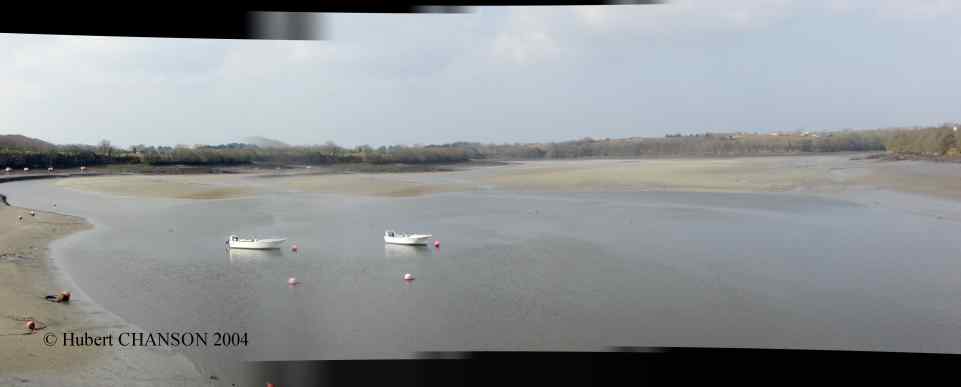 Coastlines of France
c10- Cote de Granite Rose : Ploumanach (Bretagne, France)
in Dec. 1994, lighthouse, granite
coast.
c11- Mont Saint Michel (Bretagne, France)
Photo No. 1 : in Dec. 1994. Photo No. 2
: Mont St Michel at low tide on 4/2/2004. Photo
No. 3 : Ile de la Tombelaine, North of Mt St Michel at low tide on
4/2/2004. Photo No. 4 : during the
ebb tide on 7 March 2004.
Photo No. 11 : view at high
tide on 24 June 2008 (neap tide). Photo
No. 12 : transient front in the Couesnon river estuary on 24 June
2008 at high tide, view from the Mont Saint Michel monastery. Photo
No. 13 : Transient fronts and plunge point line(s) in the Baie du
Mont Saint Michel in 24 June 2008 at high tide under neap tide
conditions; view from Mont Saint Michel with the Ile de Tombelaine on
the top right. Photo No. 14 :
detail of a transient front plunge line on 24 June 2008 at high tide.
Moulin de Moidrey, Baie du Mont Saint Michel (France). Built in
1806 as a tower mill, and restored in 2003, the wind mill was equipped
in 1840 with wooden-slatted sails
(wings/blades) based upon the French engineer BERTON's system. The
Berton system alloes the wooden-slatted sails to be deployed or folded
from inside the mill. Photo No. 21:
view on 24 June 2008 during operation. Photo
No.
22 : details of the deploed wooden-slatted sails, restored with
Berton system.
c12- Le
Val-André (Bretagne, France)
Photo
No. 1 the beach in 1998 (Courtesy of Mrs SENLY), photograph taken
about 1.5 hours before high tide; Photo
No. 2 : Port de Piegu at half-tide. Photo
No.
3 : the beach at low tide on 3 Sept. 2000. Photo
No. 4 : beach at high tide with a strong wind on 30 Sept. 2000
(Courtesy of Mrs CHANSON). Photo No. 5
: wave reflection on 30 Sept. 2000 (Courtesy of Mrs CHANSON). The tidal
range in this part of the Baie de Saint-Brieuc may reach over 14 metres.
Photo No. 6 : beach on 28 Feb. 2004
under the snow, at mid-flood tide around 8:2am; the beach was totally
covered by snow and the event was on the national evening news (TF1,
2:00). Photo No. 7 : Port de Piegu
under snow on 28 Feb. 2004. See also the Atlantic
Wall fortification at Le Val-André in the Civil
Engineering Structures section.
c13- Le
Verdelet, Val-André (Bretagne, France)
The Verdelet may be reached on foot at
very-low tides. There is a legend that a monastery was once built on the
rock. Photo No. 1 : general view. Photo No. 2 : at low tide on 3 Sept.
2000. Gravure by Y.H. CHOU in Sept.
2000.
c14- Le
Port de Dahouet (Bretagne, France)
Photo
No. 1 : at high tide on 3 Sept. 2000. Photo
No.
2 : at low tide on 8 Sept. 2000. Photo
No.
3 : the Moulin à marées (tidal mill) with the Etang de la Flora in
foregound and the harbour of Dahouet in background in Sept. 2000.
c15- Plage des Vallées, Côtes d'Armor (Bretagne,
France). Photo No. 1 : on 28 Feb.
2004 around 8:00 am under the snow. Photo
No. 2 : wave breaking on 28 Feb. 2004 at mid flood tide, with the
glare from the sunset.
c16- Erquy
(Bretagne, France) - Le Port d'Erquy
and an "old sail" in Sept. 2000. Le Cap
d'Erquy in Sept. 2000.
c17- Aber-Ildut
(Finistère, France) - Photo No. 1 :
entrance of the Aber on 1 Mar. 2004 at mid ebb tide. Photo
No. 2 : entrance channel on 1 Mar. 2003, with the Phare du Four
("Four" Lighthouse) in background.
c18- Aber Benoît (Pays
du Léon, Finistère, France).
An aber is an estuary with the
shape of a fjord. The Aber Benoît (or Benniget)
is about 8 km long. Photo No. 1 :
Port de Stellac'h, St Pabu, on 10 March 2004 at low tide, looking
upstream. Photo No. 2 : View from
the left bank below Moulin Quinou on 10 March 2004 at low tide. Photo No. 3 : Looking downstream from
Pont de Tréglonou at low tide on 10 March 2004. Photo
No. 4 : looking downstream near the upstream of the Aber on 10
March 2004 at low tide. See also
the Atlantic Wall fortifications
around Aber Benoit and Aber Wrac'h in the Civil
Engineering
Structures section.
c19- Aber
Wrac'h (Pays du Léon, Finistère,
France). Photo
No. 1: Looking downstream at low tide on 10 March 2004 from Traon.
Photo No. 2 : Looking
upstream at low tide on 10 March 2004 from Traon. Photo
No. 3 : Looking upstream at low tide on 10
March 2004 near Kerouatz; note the Parcs à huitres (oyster farm).
See also
the Atlantic Wall fortifications
around Aber Benoit and Aber Wrac'h in the Civil
Engineering Structures section
c20- Pointe
Saint Mathieu (Pays du Léon, Finistère, France). Photo
No. 1 : light tower, navigation control tower and old monatery on
16 March 2004; the monastery was founded during the 6th century AD by
Saint Tanguy and the church building was built between the the 11th and
15th centuries. Photo No. 2 :
light tower (56 m high) in the middle of the monastery church on 16
March 2004. Photo No. 3 : Pointe
St Mathieu on 16/03/2004 at high tide looking South. Photo
No.
4 : Tourelle Les Vieux Moines about 1 km West-South-West of Pointe
St Mathieu on 16 March 2004 at high tide. See
also the Atlantic
Wall fortification next to Pointe Saint
Mathieu (Les Rospects, Kéringar) in the Civil
Engineering Structures section.
c21- Pointe du
Petit Minou, Pointe du Grand Minou and Plage du Minou (Pays du Léon, Finistère,
France). Photo
No. 1 : light tower and fort viewed from Pointe du Grand Minou
(Hameau de Toulbroc'h) at 13:15 (mid flood tide) on 18 March 2004. Photo No. 2 : Pointe du
Grand Minou and Plage du Minou at 13:00 (mid flood tide) on 18
March 2004; note surfers on foreground right. Photo
No. 3 : Plage du Minou at low tide on 24 march 2004. Photo
No. 4 : dune bed forms with ripples at Plage du Minou on 24 March
2004 at low tide. Photo
No. 5 : dune bed forms with ripples at Plage du Minou on 24 March
2004 at low tide. Photo
No. 6 : dune bed forms with ripples at Plage du Minou on 24 March
2004 at low tide; details of one bed form with key ring for scale. See also the Atlantic
Wall fortification at Pointe du Petit
Minou in the Civil
Engineering Structures section. Read "Pointe
du Petit Minou and Phare, Goulet de la Rade de Brest, Bretagne, France"
in Journal of Coastal Research
2006 (PDF file at
EprintsUQ).
c22- Sillon de
Talbert, Pleubian, Côtes d'Armor (Bretagne, France). The Sillon du Talbert is a natural thin 3
km long tongue made of 'galets' (pebbles about 5 to 20 cm) and sand. It
is located at the tip of a peninsula between the estuaries of the river
Jaudy (Le Jaudy) et Trieux (Le Trieux) next to Ile de Bréhat. At the end
of the Sillon, there is an archipel of islands and rocks called
"Archipel d'Ollone" (Ollone archipel), also called the Talbert islands
(Iles de Talbert) for local people. The Sillon du Talbert (or Sillon de
Talbert) is an important reserve of flora and fauna. The Sillon was
damaged by locals using stones for construction until 1928, the German
using stones for the Ile Blanche (et Ile à Bois ?) bunker system
construction in 1943 as part of the Atlantic wall. Photo
No. 1 : Start of the Sillon, looking NW at NW slope of
Sillonon 16/04/2004 at low tide. Photo
No. 2 : detail of SE slope looking NE at low tide on 16/04/2004. Photo No. 3 : Rocher Min Buas at low
tide, North of Sillon de Talbert. Photo
No. 4 : preferential flows below protection riprap near start of
Sillon, NW slope at low tide on 16/04/2004. Some info {http://www.conservatoire-du-littoral.fr/front/process/}.
See also the Atlantic
Wall fortifications around Pleubian (Pleumeur-Gautier, Créac'h Maout)
in the Civil Engineering
Structures section.
c23- Plage
du
Port-Morvan, Côtes d'Armor (Bretagne, France). Located 1.2 km Sout-West of Lle Port de
Dahouët and 2km Sout-West of Plage du Val-André, the small beach was blocked
by an anti-tank wall, with a small opening in the middle and a machine
gun position on the top. There was no other fortification. Photo
No. 1 : German anti-tank wall on Sat. 1 May 2004 during mid ebb
tide looking at the sea; the machine gun site is on the right. Photo
No. 2 : German anti-tank wall on Sat. 1 May 2004 during mid ebb
tide.
c24- Phare de Cordouan,
Gironde (France).The lighthouse of Cordouan was built between 1584 and
1611 at the mouth of the Gironde estuary 7 km offshore. It was
heightened in 1789 to its present form. It is 67.5 m high and its light
is seen at more than 40 km. Note that the prisms were hand-cut by
Augustin FRESNEL himself. The lower cylindrical section of the
lighthouse is the original edifice and the upper conical shape is the
extension completed in 1789. The Cordouan lighthouse is heritage-listed
since 1862. Photo No. 1 : Phare de
Cordouan at high tide on 5 July 2008 about 11:00. Photo
No. 2 : Phare de Cordouan at mid-ebb tide on 5 July 2008 about
13:00. Photo No. 3 : view on 5 July
2008. Photo No. 4 : details of the
beacon and its Fresnel prisms on 5 July 2008. Photo
No.
5 : view at low tide on 5 July 2008; note the reef around the
lighthouse foundation. Photo No. 6
: view at low tide from the Cordouan eastern sand bar formation on 7
July 2008. Photo No. 7 : Cordouan
eastern sand bar at early ebb tide; note people disembarking on the sand
bar to access to Cordouan. Photo No. 8
: Cordouan southern sand bar; note the access jetty at high tide on the
bottom left and the boats in the mooring/refuge on the North of the
lighthouse; this photograph was about 10 minutes after Photo
No. 7.
ce25- Pointe de Grave,
Gironde (France). Photo No. 1 :
view on 5 July 2008 around 9:30. Photo
No. 2 : Ferry between Royan and Pointe de Grave, leaving Pointe de
Grave on 5 July 2008 about 13:30.
ce26- Pointe de la Coubre,
Charente (France). Photo No. 1 :
Phare de la Coubre on 20 July 2008; completed in 1905, the
lighthouse is 58.5 m above ground (64 m above high water level); it was
originally built at 1.8 km from the shoreline. Photo
No. 2 : German bunker (Atlantic wall) partly buried in the beach;
it is now at the high water level line. Photo
No. 3 : German bunkers from the Atlantic wall on the Plage de la
Grande Cote on 20 July 2008.
ce27- Dune du Pilat (Pilat
Sandbank), France. The Dune du Pilat, also called Dune de Pyla, is
Europe's largest aeolian sand dune. It is 105 m high, 200 m wide at the
base and 2,700 m long, and it contains over 60 Mm3 of sand. Photo
No. 1 : view fron Cap Ferret at high tide on 7 Sept. 2008. Photo
No. 2 : looking South at the dune and forest behind on 7 Sept.
2008. Photo No. 3: looking at the
Banc d'Arguin on 7 Sept. 2008 at mide ebb tide. Photo
No. 4 : paragliders above the dune on 7 Sept. 2008.
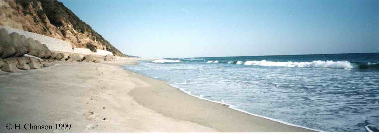 Tide
calculations worldwide (in French)
Tide
calculations worldwide (in French)
Atlantic wall (Mur de l'Atlantique) along French coastlines
See the Atlantic
Wall section in Civil
Engineering Structures.
Read Coastal
Observations: The Atlantic Wall in Bretagne Nord (North Brittany),
France (Shore & Beach,
Vol. 72, No. 4, pp. 10-12 & Front cover)
aw1- Les Rospects,
Pointe Saint-Mathieu, France. The battery included at least four 150
mm gun bunkers and several other fortifications. Photo
No.
2 : 150 mm gun bunker No. 1 on
15/04/2004. Photo No. 4 :
fortification in frot of the 150 mm gun bunkers on 15/04/2004, with
Tourelle Les Vieux Moines in background.
aw3- Pointe
du Petit Minou, Goulet de Brest, France. Based in and above
the Fort du Minou, the battery protected the entrance to the Goulet de
Brest. Photo No. 1 :
105 mm gun German bunker on 14/04/2004.
Photo No. 2 Phare du Petit Minou and Fort from a 105 mm
gun bunket on 20/04/2004 at low tide. Photo
No. 3 : Observation and transmission tower inside Fort du Petit
Minou on 20/04/200, viewed from Phare du Petit Minou.
aw4- Pointe de
Portzic, Goulet de Brest, France.
Based below the phare du Portzic, the battery was placed at the end of
the Goulet de Brest. It waa designe to include four 105 mm gun
bunkers, three 88 mm gun bunkers, and three 150 mm gun bunkers. Photo
No. 1 : 105 mm gun German bunker on 14/04/2004. Photo
No. 2 : 88 mm gun German bunker on 14/04/2004 just below Phare
de Portzig. Photo No. 3 : View of
the Goulet de Brest from a 105 mm gun German bunker on 14/04/2004.
aw5- Plage
des
Vallées, Côtes d'Armor (Bretagne,
France). A 10 km long beach from Pléneuf-Val-André
to Equy included Plage des Vallées, Plage de
Nantois, Plage de la Ville-Berneuf, Caroual. The Western end was
protected by a strong bunker overlooking the Plage
des Vallées. Photo
No. 1 : view from the roof the bunker looking at Plage des
Vallees on 28/2/2004 at mid flood tide, with the beach under snow
after Northernly snow falls. Photo No.
2 : View of a communication tunnel from the beach; parts of the
blockhaus broke and landed on the beach in the mid 1990s. Photo No. 4 :
observation bunker , with machine gun bunker behind at St Pabu beach
on 18 Apr. 2004. Photo No. 5 : St
Pabu beach from inside the machine gun bunker on 18 Apr. 2004, with
the Verdelet island in background. Photo
No. 6 : bunker (blockhaus) for gun above St Pabu beach on 18
Apr. 2004.
aw6- Plage du
Val-André, Côtes d'Armor (Bretagne, France).
The 2 km long beach was protected by at least 3 concrete bunker
systems. One series of bunker was located at the Pointe des Murs
Blancs; it include a casemate for machine gun and probably a larger
bunker above. There was a concrete bunker (blockhaus) about middle of
the beach (presently rue des Bignons), and there was a bunker system
at Pointe de Pléneuf (also called Château-Tanguy) with an observation
post overlooking both Plage du Val-André and Plage des Vallées. Photo
No 1 : Les Mur Blancs, German bunker for machine gun on 18 Apr.
2004. Photo No. 2 : Looking NE at
the Val-André beach from the casemate at high tide on 18 Apr. 2004.
aw8- Pointe de Kermorvan, Le
Conquet, France. The Pointe de Kermorvan was a heavily fortified position
defending the Northern entrance of Le Conquet harbour. The Kermorvan
peninsula is covered by numerous German fortifications, including two
105-mm guns at Fort de Kermorvan, two large bunkers for guns, several
Tobruk bunkers, especially on the Northern part of the peninsula, and
one large circular turret (at least 2 levels deep) facing le Fort de l'Ilette on the Northern part of
peninsula. Photo No. 1 : 105 mm
gun German bunker on 19/04/2004, North of Fort de Kermorvan, with
Phare de kermorvan on the right. Photo
No. 2 : Tobrouk position above the Phare de Kermorvan on 19 Apr.
2004. Photo No. 3 : Tobrouk
position overlooking the Fort de L'ilette on 19 Apr. 2004.
aw9-
Pointe des Renards,
Le Conquet, France. The Pointe des Renards was on the Southern side of
Le Conquet harbour, facing the Fort de Kermorvan. The Pointe was
equipped with at least two bunkers for guns with an additional
fortification further South. Photo
No. 1 : German bunker for gun, Pointe des Renards on 20/04/2004;
the casemate faced South. Photo No. 2
: Pointe
des Renards et Tourelle des Renards on 20/04/2004 at low tide, note
the German bunker on the far right.
aw11-
Aber Wrac'h, Pays du
Léon, Bretagne, France. The entrance of the
Aber Wrac'h was protected by several fortifications. At least two
bunkers were located on Fort de Cézon, and
there were several small bockhaus on the left entrance banks. One
unusual bunker covered both entrances of Aber Wrac'h and Aber Benoit.
Photo No. 1 : German blockhaus
covering both entrances of Aber Benoit and Aber Wrac'h on 22/04/2004
at mid ebb tide; note the roof shape to keep some grass or sans as
camouflage; it was unusual that there were two wide openings on left
and right covering respectively the Aber Benoit and Aber Wrac'h
entrances; the visible opening covered the Aber Benoit. Photo
No. 2 : looking at Aber Wrac'h entrance from inside the bunker
on 22/04/2004 at mid ebb tide, with the Phare de L'Ile Vierge in
background. Photo No. 3 :
observation bunker on 22/04/2004 covering the entrances of both Aber
Benoit and Aber Wrac'h (mid ebb tide); the previous bunker is in
background.
aw12- Pointe
de
la Coubre, Charente (France). Photo
No.
1 : German bunker (Atlantic wall) partly buried in the beach in
front of Phare de la Coubre; the bunker is now at the high water level
line. Photo No. 2 : German
bunkers from the Atlantic wall on the Plage de la Grande Cote on 20
July 2008.
Coastlines
of
China
cc01- Pearl
River delta, China. Photo No. 1
: Pearl river delta in Guangzhou, in front of the Guangzhou Ramada Hotel
on 28 Nov. 2006. Photo No. 2 : Pearl river delta in Guangzhou, in front of the Guangzhou
Ramada Hotel on 28 Nov. 2006.
Humen outlet : Photo No. 11 : Humen
outlet and matsu temple, Pearl river delta on 29 Nov. 2006 around 17:00,
view from right bank. Photo No. 12 :
Old Chinese fort protecting the Humen outlet
entrance, Pearl river delta on 29 Nov. 2006; the fort was part of a
defense system of the Humen inlet entrance, and it was used in 1841 and
1856.
Macau : Photo No. 21 :
Macau, Pearl river delta on 29 Nov. 2006 at low tide. Photo
No. 22 : Macau, Pearl river delta on 29
Nov. 2006 at low tide. Photo No. 23
: Macau, Pearl river delta on 29 Nov. 2006 at
low tide.
Modaomen outlet : Photo
No.
31 : Modaomen outlet and bridge, Pearl river delta on 29 Nov. 2006
at low tide, view from the right bank.
Coastlines
of
Italy
c30- Bari,
Italy. Photo No. 1 : detached
breakwaters in front of Bari (Lungomare street) on 18 Feb. 2004. Photo
No. 2 : entrance of Bari fishing harbour on 18 Feb. 2003.
c31- Venice, Italy
and its lagoon (laguna) . Photo No. 1
: Palazzo Ducale, Piazza San Marco, Laguna Veneta on 30 June 007
around 12:00 noon. Photo No. 2 :
Grand Canal, Laguna Veneta on 30 June 007
around 12:00 noon. Photo No. 3 :
Rio deli Orso, off the Grand Canal, on 30 June
007 around 12:00 noon. Photo No. 4
: Rio di San Angelo, Laguna Veneta on 30 June 007 around 12:00 noon. Photo
No. 5 : Isola di San Giorgio Maggiore, Laguna Veneta on 30 June
2007 around 17:00. Photo No. 6 :
Isola di San Servolo, Laguna Veneta on 30 June
2007 around 17:00. Photo No. 7 :
small canal in the Lido island, Venice, Italy on 1 July 2007 around
8:30 am - Looking towards the Laguna in background. Photo
No. 8 : Certosa island, Laguna Veneta, view from Lido on 2 July
2007 around 7:00am. Photo No. 9 :
canal between Lido and Certosa islands, Laguna Veneta, view from Lido
on 2 July 2007 around 7:00am.
Coastlines
of Taiwan
ct1- Beinan
river mouth, Taitung, East coast of Taiwan. Photo No. 1 :
looking upstream at the river bed about 200 m upstream of the Pacific
Ocean on 23 Nov. 2006.
ct2- Tungkang river
estuary (Dongkan river), Pingtung county, West coast of Taiwan.
Photo No. 1 : Tungkang river at
Wulung on 18 Nov. 2006; tidal section of the river at high tide. Photo
No.2 : Fishing raft made of bamboos on Tungkang
river at Wulung on 18 Nov. 2006.
ct3- Fangshan river mouth,
Pingtung county, West coast of Taiwan. Photo
No.
1 : Fangshan river mouth, 10 km South of Tungkang on 23 Nov. 2006.
Photo No. 2 : Fangshan
river mouth on 23 Nov. 2006.
ct4- Dapeng lagoon,
Tungkang (Dongkan), Pingtung county, South-West coast of Taiwan. The
Dapeng lagoon was used during World War II by the Japanese as a seaplane
air base; it was tehn called "Datan". In 1949, the Chinese built an air
force academy on the site. It became a national scenic area in 1997. Photo No. 1 : Dapeng lagoon on 26
Nov. 2006 around 15:00, looking South West from the former air base. Photo No. 2 : Dapeng
lagoon on 26 Nov. 2006 looking North West from the former air base.
ct5- Tungkang
(Dongkan), Pingtung county, South-West coast of Taiwan. Photo
No. 1 : black sand beach on the Taiwan straight, in front of the
Dapeng lagoon on 26 Nov. 2006; swash zone around 16:00. Photo
No. 2 : black sand beach on the Taiwan
straight, in front of the Dapeng lagoon on 26 Nov. 2006; swash zone
around 16:00.
ct6- Erluanbi
(Eluan Pi), South Cape of Taiwan , Kenting,
Pingtung county,Taiwan. Photo No. 1
: lighthouse on 25 Nov. 2006, looking North. Photo
No. 2 : lighthouse on 19 Nov. 2006, looking East. Photo
No. 3 : Mount Dejian (318 m) looking North from Erluanbi; note the
"sail rock" in front of Mount Dejian on 19 Nov. 2006. Photo
No. 4 : Coral reef South of the Eluan Pi lighthouse on 25 Nov. 2006. Photo
No. 5 : Coral reef and "sea pavillon", South-West of the
lighthouse on 25 Nov. 2006. Photo No. 6
: the "sail rock" looking North from Erluanbi on
19 Nov. 2006. Photo No. 7 : Coral reef and "sea pavillon" cliff, at Erluanbi on 19 Nov. 2006.
ct7- Hualien,
East coast of Taiwan. Photo No. 1 :
Hualien harbour entrance on 22 Nov. 2006. Photo
No. 2 : Hualien harbour entrance lighhouse on 22 Nov. 2006. Photo
No. 3 : Me-Lun river mouth in front of Hualien harbour entrance on
23 Nov. 2006; note the gravel and pebble bar obstructing the river
mouth.
ct8- Sansiantai,
Taitung county, East coast of Taiwan. Located about 60 km North of
Taitung city. Photo No. 1 : East
coast looking North from Sansiantai on 23 Nov. 2006. Photo
No. 2 : Sansiantai on 23 Nov. 2006. Photo
No. 3 : Sansiantai on 23 Nov. 2006, view from the 8-arches bridge.
Photo No. 4 : White waters at the
foot of Sansiantai on 23 Nov. 2006.
Tidal bores (mascaret,
pororoca)
b1- Mascaret on the Dordogne river, at
Vayres (au Port de Saint Pardon, France) : looking
in
the bore direction, looking
upstream (Courtesy of Fabrice COLAS).
Tidal bore (mascaret) on 27
Sept. 2000 : Photo No. 1 :
arriving bore; Photo No. 2 :
kayacks and surfers; Photo No. 3 :
close to St Pardon; Photo No. 4 :
in front of St Pardon.
Tidal bore on 21
Feb. 2004 : Photo No. 1 :
arriving bore (surge Froude number about 1.05 to 1.1) at St Pardon; Photo No. 2 : bore moving upstream
towards Vayres. Photo No. 3 :
fisherman catching lamproie fish with net few minutes prior the bore
arrival between Vayres and St Pardon.
Tidal bore on 4
July 2008 : Photo No. 1 :
view from Saint Pardon : very weak undular surge. Photo
No. 2 : looking upstream towards Vayres.
Tidal bore on 20
July 2008 at sunrise : Photo
No. 1 : Dordogne river in front of Port de Saint Pardon before the
tidal bore arrival. Photo No. 2 :
ripple in the channel centreline marking the tidal bore front, view from
the left bank. Photo No. 3 : wave
breaking next to the left bank. Photo
No. 4 : whelps 60 seconds after the tidal bore front passage.
Tidal bore on 21
July
2008 at sunrise : Photo No. 1
: tidal bore front approching the jetty of Saint Pardon at 07:03. Photo
No. 2 : wave breaking at the jetty during the wave front passage.
Photo No. 3 : wave breaking on the
jetty about 58 s after the tidal bore front passage.
Tidal bore on 2
September 2008 evening : Photo
No. 1: View from Port de Saint Pardon, looking downstream. Photo
No. 2 : surfers in front of Port de Saint Pardon. Photo
No. 3 : surfers on the second wave crest passing in front of Port
de Saint Pardon.
Menhir
de Pierrefitte : neolithic mounument located at Chateau Saint
Martial, on the right bank next to the old Pierrefitte harbour which
serviced Saint Emilion up the 16th century.
b2- Mascaret on the Seine river
(France) : Photo No. 1 : at
Caudebec-en Caux around 1960, view from the bac (ferry) looking at the
right bank (Photograph by Raymond HUON, Courtesy of Sequana-Normandie) -
Photo No. 2 : Bac de Caudebec-en
Caux facing the mascaret in 1958, view from the right bank (boats and
ships had to leave the wharf to face the mascaret in a similar
way) (Copyright: Alain HUON, Courtesy of Sequana-Normandie) - Photo
No. 3 : the passage of the mascaret in the 1930s,
photograph taken at the ramp of the ferry at Yainville (France), right
bank, near the old power station (Courtesy of G. FROMAGER) - Photo
No. 4 : after the passage of the masaret looking upsteam, view
from right bank between Yainville and Jumieges, looking toward
Heurteauville; Note the quite river upstream of the bore (on the left
top) (Courtesy of Sequana-Normandie) - Photo
No. 5 : the mascaret at Aizier, near Quilleboeuf (view from left
bank) (Courtesy of J.J. MALANDAIN) - Photo
No. 6 : mascaret at Quilleboeuf (Photo I. Hernault, Le
Havre) (Courtesy of J.J. MALANDAIN) - Photo
No. 7 : the mascaret at Villequier, ancient gravure (Courtesy of
J.J. MALANDAIN) - Photo No. 8 :
mascaret on the Risle, a tributary of the Seine river at Pont-Audemer
(Collection A. Renard, editeur, Pont-Audemer) (Courtesy of J.J.
MALANDAIN). More about the Mascaret
of the Seine river ...
b3- Tidal bore near Truro (Bay of Fundy, Canada) :looking upstream, detail of bank
erosion (Courtesy of Larry SMITH). Photo
No. 3 : arriving tidal bore on the Salmon river on 22 Sept. 2001
(Courtesy of Dr M.R. GOURLAY). Photo No.
4 : sideview of tidal bore on the Salmon river on 22 Sept.
2001 (Courtesy of Dr M.R. GOURLAY)
b4 Severn river (England) : Photo
No. 1 : at Awre where the estuary is wide and shallow (Courtesy of
Professor D.H. PEREGRINE) - Photo No. 2
: further upriver where the Severn river is deeper and narrower
(Courtesy of Professor D.H. PEREGRINE).
b5- Qiantang River near
Hangzhou, China
The tidal bore on the Qiantang River near
Hangzhou, China, is known as the Hangchow or Hangzou bore. Photo No.1: Qiantang River bore at
Hangzhou CBD City Balcony on 9 October 2014. Photo
No.2: tidal bore at Qilimiao downstream of Yanguan on 11 October
2014. Photo No. 3:
tidal bore between Yanguan and Laoyanchang on 11 October 2014. Photo No. 4: breaking tidal bore
and roller between between Yanguan and Laoyanchang on 11 October 2011. Photo No. 5: tidal
bore reflection at Laoyanchang on 11 October
2011. Photo No. 6
: tidal bore impact on sluice gate structure at Jiuxi
on 11 October 2014; in the foreground, the reflected wave overtopped the
river bank, flooding the nearby arterial and causing some traffic
accident and traffic jam. Photo
No. 7: tidal bore at Meilvba overtopping a spur dyke on 12 October
2014. Photo No. 8:
tidal bore impact on the sea wall at Xinchang on 13 October 2014; the
bore was reflected on the wall and the reflection came back about 40
minutes later. Photo
No. 9: tidal bore warning sign at Meilvba
in October 2014; in this area, the embankent dyke is regularly
overtopped. Photo
No. 11 : view from the left bank (Courtesy of Dr J. Eric JONES); Photo No. 12 : another detailed view
(Courtesy of Dr J. Eric JONES).
b6- The tidal bore of the Petitcodiac river, near
Moncton (Bay of Fundy, Canada). Photo
No. 1 : in spring 1908? near Moncton, the bore height being about
1 to 1.5 m (Courtesy of the Petitcodiac Riverkeeper) - Photo
No. 2 : on 23 Mar. 2000, the bore height was estimated to be about
0.5 m. The river discharge was larger than usual because of snow melt
(Courtesy of the Petitcodiac Riverkeeper).
b7- Tidal bore of the Daly
river, Northern Territory, Australia. Photograph taken late
in 2000 when the water flow is lowest (Courtesy of Gary Higgins, The
Mango Farm).
b8- Tidal bore (mascaret) on
the Couesnon river
(France). The tidal bore is significantly weaker since the construction
of an upstream barrage. Photo No. 1
: approaching bore on 7 March 2004 around 18:20. Photo
No. 2 : bore seen from the Tour de Gabriel on 7 March 2004 (bore
flowing from right to left). Photo No.
3 : Couesnon river at low tide on 4 Feb. 2004 before the mascaret,
looking upstream from Mont Saint Michel monastery.
b9- Tidal bore of the Sélune
river, Baie du Mont Saint Michel (France). Tidal bore on
7 April 2004 : tidal range =
13.75 m (highest tidal range for 2004). Read
Coastal
Observations:
The Tidal Bore of the Sélune River, Baie du Mont Saint Michel, France
(Shore & Beach, 2004, Vol.
72, No. 4, pp. 14-16). Photo
No. 1 : Sélune river estuary, viewed from left bank at Roche-Torin
at sunrise on 7/4/04 beofre tidal bore arrival. Photo
No. 2 : tidal bore seen from Roche-Torin far away in front of Ile
de Tombelaine with seagulls (white dots) in front of the bore. Photo
No. 3 : advancing tidal bore in front of Pointe du Grouin du
Sud. Photo No. 4 : advancing
bore front viewed from Roche-Torin on 7/4/04. Photo No. 5 : advancing
bore front viewed from Roche-Torin on 7/4/04. Photo No. 6 : advancing
bore front just in front of Roche-Torin on
7/4/04. Photo No. 7 : tidal bore
advancing upstream, seen from Roche-Torin on 7/4/04. Photo
No. 8 : approaching tidal bore, one hour later, upstream of Pont
Aubaud (15th century bridge) at Pontaubault on7/4/04. Photo No. 9 : approaching tidal bore,
one hour later, upstream of Pont Aubaud (15th century bridge) at
Pontaubault on7/4/04. Photo
No. 10 : Sélune river tidal
bore approaching Pont Aubaud (15th century bridge) at Pontaubault
on7/4/04. Photo No. 11 : Sélune river tidal bore passing below
Pont Aubaud (15th century bridge) at Pontaubault on7/4/04; note the
bridge pier "knife" shape; note also that the bore became an undular
bore just downstream of the bridge, possibly because of a local scour
hole. Photo No. 12 : strong current
below Pont Aubaud (15th century bridge) on
7/4/04 after the tidal bore passage, view from left bank looking
upstream.
Tidal bore on 2 August
2008: tidal range = 12.65 m. Photo
No.
1 : Sélune river tidal
bore at Roche Torin on 2/8/08 at sunset, viewed from the left bank (bore
propagation from left to right). Photo
No. 2 : tidal bore propagation past Roche Torin on 2/8/08. Photo
No.
3 : tidal bore past Roche Torin on 2/8/08. Photo
No. 4 : Sélune
river tidal bore at Pontaubault on 2/8/08 at sunset, about 1 hour after flowing past Roche
Torin. Photo No. 5 : Sélune river tidal bore at Pontaubault on 2/8/08, approaching the
histoical Pont Aubaud (15th century bridge); note
the undular nature of the tidal bore and the whelps (éteules). Photo No. 6 :
interactions of the whelps (éteules) with the bridge piers shortly after the tidal bore front
passage on 2/8/08.
Tidal bore on 3 August
2008: tidal range = 12.65 m. Photo
No.
1 : Sélune river tidal
bore at Roche Torin on 3/8/08 shortly after sunrise, viewed from the
left bank (bore propagation from left to right). Photo
No. 2 : tidal bore propagation at Roche Torin on 3/8/08.
Comparison between field adnd laboratory measurements:
"Physical Modelling of Breaking Tidal Bores: Comparison with Prototype
Data." Journal of Hydraulic Research,
IAHR, Vol. 53, No. 2, pp. 264-273, 2015 (DOI:
10.1080/00221686.2014.989458) (ISSN 0022-1686). (Postprint
at UQeSpace) (PDF
file)
b10- Tidal bore of the
Dordogne river (France) on 27 September 2000
b11- Tidal bore of the Garonne
river (France) on 5 July 2008. Tidal bore on 5
July 2008 at Arcins (Latresnes). Photo
No. 1 : tidal bore entering the Arcins channel. Photo
No.
2 : incoming undular bore in the Arcins channel around 6:20am
looking downstream. Photo No. 3 :
whelps (éteules) behind the bore front shaking the pontoon and jetty.
Tidal bore on 5 July 2008 at Langoiran. Photo
No.
1 : very weak bore with some was breaking next to the left bank
about 7:05am, while there was no bore in the main channel nor next to
the right bank. Tidal bore on 6 July 2008 at Arcins (Latresnes). Photo
No. 1 : looking downstream at the incoming bore around 7:10am;
note the small ripple formed by the tidal bore. Photo
No. 2 : undular bore passing in front of the photographer. Photo
No. 3 : propagating bore; note the strong mixing and reflection in
the inlet in the foreground.
Tidal bore on 19 July
2008 at Podensac. Photo
No. 1 : large-scale vortical structures at the free-surface on the
channel centreline on 19 July 2008 at end of ebb tide flow (18:30)
shortly before tidal bore arrival. Photo
No. 2 : tidal bore propagation next to left bank looking
dowsntream at 18:43. Photo No. 3 :
details of the bore front impact on the left bank.
Tidal bore on 20 July
2008 at Langoiran. Photo No. 1
: surfer riding the bore front next to the left bank. Photo
No. 2 : surfer getting back to the boat after the ride.
Tidal bore on 2
September 2008 at Podensac. Photo
No.
1 : Advancing bore with surfers. Photo
No. 2 : surfers next to the left bank.
Tidal bore on 3
September 2008 at Baurech. Photographs taken from a kayack
surfing the Garonne River bore. Photo
No. 1 : looking towards the left bank while riding ahead of the
first wave crest. Photo No. 2 :
looking towards the right bank at several kayacks riding ahead the first
wave crest. Photo No. 3 : riding
the whelps behind the bore front.
b12- Tidal bore of the Arguenon
River, Bretagne (Brittany). Photo
No.
1 : tidal bore at Les Pierre Sonantes, le Guildo on 15 Oct. 2008.
Photo No. 2 : tidal bore betwen Le
Guildo and Créhen.
b13- Tidal bore of the Frémur
Creek, Côtes d'Armor, Bretagne (Brittany). Photo
No. 1 : tidal bore at Port-à-la Duc on 15 Oct. 2008. Photo
No. 2 : tidal bore upstream of Port-à-la
Duc on 16 Oct. 2008.
More about Tidal
bores, Mascarets and Pororoca ...
More about the Mascaret
of the Seine river ...
More about Tidal
bore hydraulics ...
Whirlpools
(Maelstrøm)
wh1- Naruto whirlpools. On Wed. 17 Oct. 2001,
during the ebb flow (current from Insland Sea to Pacific Ocean), a
freighter became trapped in the vortices, its bow hit the rocks and the ship was grounded until the
next high tide. Photo No. 1 :
general view from Ohnaruto bridge.
Photo No. 2 : whirlpools and
vortices with a freighter in background, note the large eddy (over
50-m diameter) on the right. Photo
No. 3 : tourist boat in the middle of the whirlpools. Photo
No. 4 : street of vortex. Photo
No. 5 : Freighter and whirlpools. Photo
No. 6 : whirlpool in foregound right with stranded freighter in
background. Photo No. 7 :
freighter trapped in Naruto whirlpools which became grounded beneath
the bridge. Photo No. 8 :
grounded bow of the freighter. Photo
No. 9 : Flood flow on 9 July 2002 beneath the bridge (Courtesy
of Drs ICHIMIYA and BROWN). Photo No.
10: Turbulent vortices during the flood flow on 9 July 2002
(Courtesy of Drs ICHIMIYA and BROWN).
wh2- Whirlpools at Naruto (Japan) on
17 October 2001
"Experiencing
Naruto
Whirlpools." IAHR Newsletter, Vol. 40, No. 2, pp. 17
& 28-29. (Download PDF
file)
More
about Whirlpools ...
Presentation
ce1- Pont du Gard,
Nîmes aqueduct, France - View from the right bank in June 1998.
ce2- Horyuji temple, Nara Prefecture, Jaoan. The
world's oldest wooden structures (Asuka period mid 6th - beginning 8th
century AD) selected by UNESCO as part of the World Heritage. Photo
No. 1 : Saiin Garan (Western preccint) : Daikòdò (Great Hall),
Heian period (beginning of 8th - end of 8th century AD) on 18 Oct. 2001.
Struck by lightning in 925. Rebuilt in 990. Photo
No. 2 : Saiin Garan : Kondò (Main Hall), Asuka period (Mid
6th - beginning of 8th century AD) on 18 Oct. 2001. Photo
No. 3 : Saiin Garan : Gojù-no-Tò (5 storey pagoda), Asuka period
(Mid 6th - beginning of 8th century AD), 31.5 m high on 18 Oct. 2001. Photo No. 4 : Chùgùji (Chùgù temple) :
Tòin Shòrò (Bell House of the Eastern Preccint), Kamakura period
(Late 12th - early 14th century AD) on 18 Oct. 2001. The bell (inside)
is from the Nara period.
ce3- Hama-matsu castle (AD 1570, Japan) - The
castle stands on unbonded rock foundation. The method of building
stonework is called "Nozura-zumi". The castle was rebuilt after WWII. Photo No. 1 : castle during the cherry
blossom on 1 Apr. 1999. Photo No.2 :
detail of the unbonded rock foundation on 1 Apr. 1999.
ce4- Sanjusangen-do temple
(AD 798/last rebuilt 1633), Kyoto, Japan. Earthquake resistant building,
constructed on timber piles set in a pit filled with superposed
layers of sand and clay.
ce5- Eiffel tower (1889, France). Designed by
Gustave EIFFEL (1832-1923) for the Centennial Exposition of 1889 to
commemorate the French Revolution, the tower is 300-metre high made of
open-lattice wrought iron. It was the tallest building in the world
until 1929. Photo No. 1 : Eiffel
tower in Aug. 1996 (Courtesy of Mr and Mrs CHANSON).
ce6- OhNaruto bridge, Japan. Also called Onaruto
bridge, it links Awaji and Shikoku islands across the Naruto kaikyo, or
Naruto strait, world-known for the Naruto
whirlpools. Completed in 1985, the Ohnaruto bridge was designed to
carry both cars and trains on the upper and lower decks respectively.
The train link was never completed and the newer Akashi bridge does not
carry trains. The bridge's lower deck carries today water between Awaji
and Shikoku islands, and the tourist walkway. Photo
No 1 : looking from the Southern end on 17 Oct. 2001. Photo
No. 2 : view from the Southern abutment, note the freighter which
became trapped in the whirlpool vortices and grounded during the ebb
flow on 17 Oct. 2001.
More on
Ohnaruto bridge : introduction,
drawings.
More
on Naruto Strait : information.
More
on Naruto Whirlpools...
Read
more in Bridges
in Japan.
ce7- Akashi bridge, Japan. Connecting Awaji island
to Honshu, it is the world's longest suspension bridge (3.9 km long).
Construction started in 1986 and was completed in 1998. The bridge
length was expanded by 1 m during the 1995 Kobe earthquake. Photo
No. 1 : looking from the Northen end on 16 Oct. 2001.
More on Akashi
bridge : general
information, technical
information. Read more
in Bridges in
Japan. Read more in Structurae database
...
ce8- Grande Arche de la Défense, Paris, France - La Grande Arche is located in La
Défense, a western suburb of Paris. Completed in 1989, the
building is 110.9 m high, 112 m long and 106.9 m wide. The arch is
inclined with a 6.33º towards the "Grand Axe" of Le Louvre museum,
The Obélisque, the Champs Elysées, the Arc de Triomphe and the Avenue de
la Grande Armée. Shortly after completion, very strong winds were felt
at the bottom of the Arch. This was caused by the natural strong winds
experienced at La Défense associated by a Venturi effect induced by the
arch shape. As a result, a 2,300 m2 surface area membrane ( ) was
installed at the foot of the arch. The membrane is called Les Nuages
("The Clouds"). Photo
No. 1 : looking West on 4 May 2003 (Courtesy of Mr and Mrs
CHANSON).
More on La Grande Arche : {http://www.structurae.de/en/structures/data/str00133.php},
{http://www.structurae.de/en/structures/data/str00134.php}
ce9- Pont de Normandie, France - Completed in
1995, the Pont de Normandie is located next to the Seine river mouth. It
is a suspension bridge. The total length is 2141 m and the central span
is 856 m long. The main deck is 52 m above the highest water levels
while the pylon height is 214.77 m. There are a total of 184 suspension
cables. Cable lenghts range from 95 to 450 m. Part of the deck
cantilevering out from the pylons was built as a hollow box made of
prestressed concrete, but about two thirds of the deck were made of a
steel. The estuary of the Seine river is well-known for strong Westerly
winds and the bridge was designed to sustain wind speeds of up to 300
km/h. The bridge deck was streamlined to reduce the wind drag and its
design was tested in wind tunnel. The wind reference velocities were an
average velocity of 35.3 m/s at 10 m/s above ground, 44 m/s at deck
level and 49 m/s at the top of pylon (210 m above water). The bridge
deck is a box-girder to increase the torsional rigidity of the bridge
and to limit the first torsional period to less than half of the first
vertical flexion period. The deck was streamlined to reduce wind forces,
with the box-girder height of less than 3.0 m. The design was aimed to
reduce vortex shedding by increasing the width to height ratio of the
deck. The pylon shape was selected to limit second order effects and to
increase its structural capacity to resist wind loads. Although the
vibration periods of the cables would have been about 4 seconds, four
damping ropes were installed to interconnect the cables and to reduce
the first period to about 1.25 seconds.
Photo No. 1 : looking North from the
left bank on 2 May 2003 (Courtesy of Mr and Mrs CHANSON). Photo
No. 2 : looking South at the Northern pylon on 2 May 2003
(Courtesy of Mr and Mrs CHANSON).
More on the Pont de Normandie : {http://www.structurae.de/en/structures/data/str00048.php},
{http://www.structurae.de/en/refs/subjects/sub0107.php},
{http://www.sequana-normandie.com/}
ce10- Biosphère,
Montréal (Canada). Built on the île Sainte Hélène, the biosphere was designed by architect Buckminister FULLER and completed
in 1967 for Expo 67. Photo No. 1
: Biosphere on 8 May 2002. Photo No. 2
: Biosphere on 12 July 2002. Photo No.
3 : Detail of the structure on 12 July 2002.
ce11- Pont
C.N.
du Port, Montréal (Canada).
Pivoting railway steel bridge above Lachine Canal
downstream of Ecluse de Saint-Gabriel. Photo
No. 1 : open bridge structure and Lachine canal on 8 May 2004. Photo No. 2 : looking
downstream of Saint Gabriel lock on 8 May 2004; the pivoting bridge is
in between a newer concrete road bridge (Pont Wellington) and a steel
railway bridge (Pont C.N. Wellington).
ce12- Grain stores and
grain elevators, Montréal (Canada). The
grain stores at Parc du Moulin à Vent were built
in 4 stages between 1903 and 1958, to store grain which arrived frorm
Western Canada and departed by Sea. The most recent parts were made of
reinforced concrete and comprised 115 vertical chambers, each 30 m deep
and up to 8 m in diameter. Due to changes in the global grain market,
the elevator became obsolete and was closed in 1996. Cited by architects
such as Grosplus and La Corbusier, the North-American grain elevators
were a major inspiration for the Modernist movement. Photo
No. 1 : grain stores at Parc du Moulin à Vent on 8 May 2002, with
Lachine canal in foreground.
ce13- Three
Gorges
Project and Dam (Yichang, China, 2002-2007). Concrete gravity
dam. Length: 2300 m, Height: 181 m. Powerplant: 32 Francis turbines (700
MW each). Photo No. 1 : Overall
view of the scale model of the project on 20 Oct. 2004, looking from the
right bank; the dam wall is in white. Photo
No. 2 : Dam wall viewed from the left abutment on 20 Oct. 2004. Photo No. 3 : Construction of the third
section on 20 Oct. 2004; view from the dam crest above the spillway
section, looking towards the right abutment. Photo
No. 4 : Navigation lock on 20 Oct. 2004; the navigation lock
is a two-way system, with 5 locks each; each lock is 280 m long and 34 m
wide. Photo No. 5 : Three Gorges
Reservoir on 20 Oct. 2004, looking from the right bank at a
hydrofoil passenger ship. Photo No. 6:
scour outlet discharge below the spillway section on 20 Oct. 2004 (Q =
7000 m3/s, V = 35 m/s). Photo No. 7 :
high-velocity flow from an outlet sluice on 20 Oct. 2004 (V = 35 m/s);
note the large amount of 'white waters' highlighting strong free-surface
aeration. Photo No. 8 : free-surface
aeration along the bottom outlet jet flow downstream of the spillway
section on 20 Oct. 2004 (V = 35 m/s). Photo
No. 9: scale model of a 700 MW Francis turbine on 20 Oct. 2004.
ce14- Eleanor Schonell Bridge,
Brisbane QLD (Australia) - Opened on 17 December 2006, the bridge is
designed to carry buses, bicycles and pedestrians
across the Brisbane River linking Dutton Park to
the University of Queenland St Lucia campus. The cable-stayed bridge has
two 70-m high piers and a 114 m span. During construction, and prior to
naming, it was nicknamed the "Green Bridge". The bridge length is 516 m
at deck level, that is 11.5 m above the water at high tide. The
cable stays were post-stressed at 45% of their ultimate capacity . Photo
No. 1 : view on 15 August 2006, looking at the underside from the
left pier foot. Photo No. 2 :
looking at the deck and right pier from the left pier on 15 Aug. 2006
with some 4th Year UQ Civil Engineering students. Photo
No. 3 : looking towards the left bank on 15 Aug. 2006. Photo
No. 4 : details of the cable anchor on the left pier on 15 Aug.
2006. Photo No. 5 : cable "dead"
anchor near the right bank on 15 Aug. 2006. Photo
No. 6 : skeleton of the central key section installed on
11Aug. 2006; photograph taken on 15 Aug. 2006 from the ferry looking
upstream at the steel structure; a footbridge allowed access from one
end of the other of the bridge .Photo No. 7 : looking at the right pier and
the stayed cables from the middle span on 15 Aug. 2006; note some cable
sagging.
Photo No. 10 : view from left bank on
6 Oct. 2005. Photo No. 11 :
construction of the bridge piers on 19 Jan. 2006, viewed from left bank.
Photo No. 12 : view from the left
bank on 21 Feb. 2006. Photo No. 13 :
looking upstream at the bridge construction on 10 Apr. 2006. Photo
No. 14 : view from left bank on 9 May 2006. Photo
No. 15 : view from the left bank (Dutton Park ferry terminal) on
26 June 2006.
Photo No. 16 : view from St Lucia, on
the official opening on 17 Dec. 2006. Photo
No.
17: view from Dutton Park on the 17 Dec. 2006. Photo
No. 18 : detail of a single strand; each cable stay includes
either 31 strands (short stay) or 37 strands (long stay); the ultimate
capacity of a strand is 28 tonnes and the fatigue resistance is
2,000,000 cycles. Photo No. 19 :
Commemorative certificate of the bridge opening on 17 Dec. 2006.
ce15- Phare
de
Cordouan, Gironde (France).The lighthouse of Cordouan was built
between 1584 and 1611 at the mouth of the Gironde estuary 7 km offshore.
It was heightened in 1789 to its present form. It is 67.5 m high and its
light is seen at more than 40 km. Note that the prisms were hand-cut by
Augustin FRESNEL himself. The lower cylindrical section of the
lighthouse is the original edifice and the upper conical shape is the
extension completed in 1789. The Cordouan lighthouse is heritage-listed
since 1862. Photo No. 1 : Phare de
Cordouan at high tide on 5 July 2008 about 11:00. Photo
No. 2 : Phare de Cordouan at mid-ebb tide on 5 July 2008 about
13:00. Photo No. 3 : view on 5 July
2008. Photo No. 4 : details of the
beacon and its Fresnel prisms on 5 July 2008. Photo
No.
5 : view at low tide on 5 July 2008; note the reef around the
lighthouse foundation. Photo No. 6
: view at low tide from the Cordouan eastern sand bar formation on 7
July 2008. Photo No. 7 : Cordouan
eastern sand bar at early ebb tide; note people disembarking on the sand
bar to access to Cordouan. Photo No. 8
: Cordouan southern sand bar; note the access jetty at high tide on the
bottom left and the boats in the mooring/refuge on the North of the
lighthouse; this photograph was about 10 minutes after Photo
No. 7.
Atlantic wall (Mur de
l'Atlantique)
The
German Atlantic wall (Atlantikwall in German, Mur de l'Atlantique in
French) was build by the German occupation forces in the period
1941-1944 along the coasts of France, Belgium, Netherlands, Germany,
Norway and Denmark. Its main goal was to prevent the Allied landings.
(Ref. {http://www.atlantikwall.net/},
{http://perso.wanadoo.fr/passion.histoire/mur.htm},
{http://www.atlanticwall.dk/})
Read Coastal Observations:
The Atlantic Wall in Bretagne Nord (North Brittany), France (Shore & Beach, Vol. 72, No. 4,
pp. 10-12 & Front cover)
aw1- Les
Rospects, Pointe Saint-Mathieu, France. The battery included at
least four 150 mm gun bunkers and several other fortifications. Photo
No. 1 : Rospects German Blockhaus, on 15/04/2004 around 20:30;
looking East at bunkers 2, 3, and 4. Photo
No. 2 : 150 mm gun bunker No. 1 on
15/04/2004. Photo No. 3 : 150 mm
gun German bunker No. 2 on 15/04/2004, tunnel to the gun station. Photo
No. 4 : fortification in frot of the 150 mm gun bunkers on
15/04/2004, with Tourelle Les Vieux Moines in background.
aw2 - Batterie
de Kéringar, Pointe Saint-Mathieu,
France. The Kéringar Blockhaus system ("Graf
Spee"), Lochrist, Pointe St Mathieu was equipped with four 280 mm guns
Krupp SKL/40 which could shoot 283 kg projectile up to 27.8 km. Photo
No. 1 : 280 mm gun bunket on 15/04/2004; note the small
observation post on roof, looking East-South-East. Photo
No. 2 : 280 mm gun German bunker on 15/04/2004. Photo
No. 3 : Ammunition German bunker next to the 280 mm gun bunket on
15/04/2004, looking West; note the house roof shape for camouflage. Photo No. 4 : German Bunker for 280
mm gun fire control on 14 Apr. 2004.
aw3- Pointe
du
Petit Minou, Goulet de Brest, France. Based in and above the
Fort du Minou, the battery protected the entrance to the Goulet de
Brest. Photo No. 1 :
105 mm gun German bunker on 14/04/2004. Photo
No.
2 Phare du Petit Minou and Fort from a 105 mm gun bunket on
20/04/2004 at low tide. Photo No. 3
: Observation and transmission tower inside Fort du Petit Minou on
20/04/200, viewed from Phare du Petit Minou. Photo
No. 4 : same building on 20/04/2004, note the concrete treatment
for camouflage.
aw4- Pointe de Portzic, Goulet de Brest, France. Based below the phare du Portzic,
the battery was placed at the end of the Goulet de Brest. It waa designe
to include four 105 mm gun bunkers, three 88 mm gun bunkers, and three
150 mm gun bunkers. Photo No. 1 :
105 mm gun German bunker on 14/04/2004. Photo
No. 2 : 88 mm gun German bunker on 14/04/2004 just below Phare de
Portzig. Photo No. 3 : View of the
Goulet de Brest from a 105 mm gun German bunker on 14/04/2004.
aw5- Plage
des
Vallées, du Nantois, de la Ville-Berneuf, de St Pabu and de Caroual,
Côtes d'Armor (Bretagne, France). A 10 km long
beach from Pléneuf-Val-André to Erquy included Plage
des Vallées, Plage du Nantois, Plage de la Ville-Berneuf, Plage de St
Pabu and Caroual. The Western end was protected by a strong bunker
overlooking the Plage des Vallées. In addition, the beaches were covered by three German army artillery batteries of four
155-mm guns each, located at La Croix des Landes, Le Souchay and Les
Petites Landes about 3-4 km inland. At St Pabu,
the fortification system consisted of at least 3 bunkers for
observation, machine gun and gun. Photo
No. 1 : view from the roof the bunker looking at Plage des Vallées on 28/2/2004 at mid flood tide,
with the beach under snow after Northernly snow falls. Photo
No. 2 : View of a communication tunnel from the beach, Plage des Vallées; parts of the blockhaus broke and landed on the beach in the
mid 1990s. Photo No. 3 : German
bunker for machine gun looking NE on 18 Apr. 2004;the blockhaus
protected the St Pabu beach toward Plage des Vallées. Photo
No. 4 : observation bunker , with machine gun bunker behind at St
Pabu beach on 18 Apr. 2004. Photo No. 5
: St Pabu beach from inside the machine gun bunker on 18 Apr. 2004, with
the Verdelet island in background. Photo
No. 6 : bunker (blockhaus) for gun above St Pabu beach on 18 Apr.
2004. Photo No. 7 : Looking at gun
opening from inside the bunker (blockhaus) for
gun above St Pabu beach on 18 Apr. 2004. Photo
No. 8 : Details of steel anchors for camouflage nets, bunker (blockhaus) for gun above St Pabu beach on 18 Apr.
2004.
aw5a- La Croix
des Landes, Saint-Alban, Côtes d'Armor (Bretagne, France). German artillery fortification for four
155-mm guns covering both Plage du Val-André and Plage des Vallées. In addition
of four blockhaus, there were fire control and observation bunkers near
Le Péhouët overlooking the township of Pléneuf and both beachfronts. Photo
No. 1 : side view of the four 155-m gun bunkers on 23 Apr. 2004. Photo No. 2 : gun opening of bunker
No. 3 on 23 Apr. 2004. Photo No. 3 :
Panoramic view from observation bunker on 23 Apr. 2004, overlooking Plage du Val-André (on left) and Plage des Vallées (on right); the houses are part of the
township of Pléneuf.
aw5b- Le
Souchay, Erquy, Côtes d'Armor (Bretagne, France). German artillery
fortification for four 155-mm guns covering the Plages des Vallées, du Nantois, de la
Ville-Berneuf, de St Pabu and de Caroual. Photo
No. 1 : Bunker No. 4, looking at the back on Fri. 30 Apr. 2004;
note the cracks on the corners caused by some ammunition explosion in
1944. Photo No. 2 : Looking West of
side of bunkers 1, 2 and 3 on 1 May. 2004 at sunrise.
aw6- Plage du
Val-André, Côtes d'Armor (Bretagne, France). The
2 km long beach was protected by at least 3 concrete bunker systems. One
series of bunker was located at the Pointe des Murs Blancs; it include a
casemate for machine gun and probably a larger bunker for 50-mm gun
above. There was a concrete bunker (blockhaus) about middle of the beach
(presently rue des Bignons), and there was a large bunker system at
Pointe de Pléneuf (also called Château-Tanguy) with an observation post
overlooking both Plage du Val-André
and Plage des Vallées. In addition, the beach
was covered by German army artillery (four 155-mm guns) located at La
Croix des Landes, 5 km inland. Photo
No 1 : Les Mur Blancs, German bunker for machine gun on 18 Apr.
2004. Photo No. 2 : Looking NE at
the Val-André beach from the casemate at high tide on 18 Apr. 2004.
aw7- Sémaphore de Créac'h
Maout, L'Armor, Pleubian, Côtes d'Armor (Bretagne, France). A radar station and observatory were
stationed at Sémaphore, protected by a 105-mm gun bunker and some
machine-gun bunkers. Photo
No. 1: Sémaphore de Créac'h Maout, looking West on 16/04/2004. More info: {http://perso.wanadoo.fr/passion.histoire/mur.htm}.
aw8- Batterie
de l'Enfer, Pleumeur-Gautier, Côtes
d'Armor (Bretagne, France). The Batterie de
l'Enfer, at Pleumeur-Gautier, was designed for four155-mm gun bunkers
protecting the river mouth of the Jaudy (Le Jaudy) and Trieux (Le
Trieux) rivers. It was built and designed for the Army. Two bunkers were
directed to protect the Jaudy river entrance, and another 2 for the
Trieux river entrance. Completed in 1944 just before the Allied landing,
no 155 mm gun was ever installed. Photo
No. 1 : Looking at the back of all 4 German bunkers on 16/04/2004.
Photo No. 2 : Gun opening of a bunker
on 15/04/2004. More info: {http://perso.wanadoo.fr/passion.histoire/mur.htm}.
aw9- Pointe de Kermorvan,
Le Conquet, France. The Pointe de Kermorvan was a heavily fortified position
defending the Northern entrance of Le Conquet harbour. The Kermorvan
peninsula is covered by numerous German fortifications, including two
105-mm guns at Fort de Kermorvan, two large bunkers for guns, several
Tobruk bunkers, especially on the Northern part of the peninsula, and
one large circular turret (at least 2 levels deep) facing le Fort de l'Ilette on the Northern part of peninsula.
Photo No. 1 : 105 mm gun German
bunker on 19/04/2004, North of Fort de Kermorvan, with Phare de
kermorvan on the right. Photo No. 2
: Tobrouk position above the Phare de Kermorvan on 19 Apr. 2004. Photo
No. 3 : Tobrouk position overlooking the Fort de L'ilette on 19
Apr. 2004.
aw10- Pointe des Renards,
Le Conquet, France. The Pointe des Renards was on the Southern side of
Le Conquet harbour, facing the Fort de Kermorvan. The Pointe was
equipped with at least two bunkers for guns with an additional
fortification further South. Photo No.
1 : German bunker for gun, Pointe des Renards on 20/04/2004; the
casemate faced South. Photo No. 2 :
Pointe
des Renards et Tourelle des Renards on 20/04/2004 at low tide, note the
German bunker on the far right.
aw11- Brest, France.
The Port de Brest was an important military harbour with a
heavily-fortified submarine base. Photo
No. 1 : Steel observation turret (Petite cloche blindée d'observation) at St-Pierre-de-Quilbignon on 20/04/2004; the turret was at the top of bunker now covered
by the street; the bell steel is more than 12 cm thick ! Photo
No. 2 : idem on 20/04/2004. Photo
No. 3 : Idem, inside view of roof details.
aw12- Aber Wrac'h,
Pays du Léon, Bretagne, France. The entrance of
the Aber Wrac'h was protected by several fortifications. At least two
bunkers were located on Fort de Cézon, and there
were several small bockhaus on the left entrance banks. One unusual
bunker covered both entrances of Aber Wrac'h and Aber Benoit. Photo
No. 1 : German blockhaus covering both entrances of Aber Benoit
and Aber Wrac'h on 22/04/2004 at mid ebb tide; note the unsual roof
shape while there were two wide openings on left and right coverign
respectively the Aber Benoit and Aber Wrac'h entrances; the visible
opening covered the Aber Benoit. Photo
No. 2 : looking at Aber Wrac'h entrance from inside the bunker on
22/04/2004 at mid ebb tide, with the Phare de L'Ile Vierge in
background. Photo No. 3 :
observation bunker on 22/04/2004 covering the entrances of both Aber
Benoir and Aber Wrac'h (mid ebb tide); the previous bunker is in
background.
aw13- Plage du Port-Morvan,
Côtes d'Armor (Bretagne,
France). Located 1.2 km Sout-West of Lle Port de Dahouët and 2km Sout-West of Plage du Val-André, the small beach was blocked by an anti-tank wall, with a
small opening in the middle and a machine gun position on the top. There
was no other fortification. Photo No. 1
: German anti-tank wall on Sat. 1 May 2004 during mid ebb tide looking
at the sea; the machine gun site is on the right. Photo
No. 2 : German anti-tank wall on Sat. 1 May 2004 during mid ebb
tide.
Great Wall of China
Mutianyu
gw1- Refurbished section : Photo
No. 1 : looking West on 19 Sep. 2001. Photo
No. 2 : looking West on 19 Sep. 2001. Photo
No. 3 : looking West on 19 Sep. 2001. Photo
No. 4 : Steep stair case (h = 0.35 m, 1V:0.7H) on 19 Sept. 2001.
Photo No. 5 : looking East on 19
Sept. 2001. Photo No. 6 : looking
East on 19 Sept. 2001. Photo No. 7
: old cannon (19 Sept. 2001).
gw2- Non-refurbished section : Photo
No. 1 : West of Mutianyu on 19 Sept. 2001. Photo
No. 2 : inside a fort (19 Sept. 2001). Photo
No. 3 : West of Mutianyu on 19 Sept. 2001.
References : {http://www.travelchinaguide.com/china_great_wall/scene/beijing/}
{http://www.travelchinaguide.com/china_great_wall/scene/beijing/mutianyu.htm}
Wind farms
wf1- Wind farm at Port-Lauragais
(France). The Centrale Eolienne d'Avignonet-Lauragais (Haute-Garonne)
consists of 10 turbines placed in 2 rows of five turbines (facing
East-South-East.Each on 20/2//2004) . Each turbine can produce 800 kW,
it has 3 blades and the diameter is 50 m. The wind farm was completed in
Nov. 2002. (Further information at http://www.espace-eolien.fr/.)
Photo No. 1 : looking at the wind
farm on 20 Feb. 2004. Photo No. 2 :
details of turbines in operation during a wind storm on 20 Feb. 2004
(high shutter speed: 1/1,000 sec.).
wf2- Wind farm at Plougras
(France). The Centrale Eolienne de Plougras (Côtes d'Armor) was
completed in 2003. It consists of 8 towers (Installed capacity : 6 MW)
on the Monts d'Arrée. Each tower can produce 750 kW, with a 48 m
diameter, type J48, 3 blades (foils) turbine. Photo
No. 1 : overall view, looking East,on 25 Feb. 2004. Photo
No. 2 : single turbine in operation on 25 Feb. 2004, looking from
the foot of the tower.
wf3- Wind farm at Plouarzel
(France). The Centrale Eolienne de Ploumoguer (Finistère) was completed
in 2003. There are 5 towers. Each turbine can produce 750 kW, and the
diameter is 48 m. Photo No. 1 : the
5 tower on 1 Mar. 2004; note that the foreground one was stopped. Photo
No. 2 : view on 1 Mar. 2004. Photo
No. 3 : View of the stopped turbine on 1 Mar. 2004. Photo
No. 4 : View from Pointe de Kermorvan on 19 Apr. 2004.
(Information on production at http://suivi-eolien.com/.)
wf4- Wind farm at Plouyé
(France) . The Centrale Eolienne de Plouyé was completed in 2002. There
is one row of 4 turbines (750 kW each). Photo
No. 1: operation on 4 March 2004. Photo No. 2 : turbine in
operation on 4 March 2004.
wf5- Wind farm at Dinéault
(France). The wind farm comprised 5 turbines (300 kW each). Photo
No. 1 : operation on 4 March 2004 in the mist, rain and wind. Photo No. 2 : rotor
in operation on 4 March 2004 in the mist, rain and wind.
wf6- Wind farm at Plouarzel, Pays du
Léon (France): turbine operation on 1 March 2004
wf7 - Winf arm at Plestan, Cotes d'Armor (France). Six turbines with an
installed capacity of 2.3 MW. Photo No.
1 : view on 26 June 2008 of 5 of the 6 turbines. Photo
No. 2 : View on 26 June 2008.
wf11- Wind farm at Kenting,
Pingtung county (Taiwan). Photo No. 1
: wind farm next to the nuclear power plant No. 3 (2 PWR reactors) on 19
Nov. 2006.
Wind mills
wf21- Moulin
de
Moidrey, Baie du Mont Saint Michel (France). Built in 1806 as a
tower mill, and restored in 2003, the wind mill was equipped in 1840
with wooden-slatted sails (wings/blades) based
upon the French engineer BERTON's system. The Berton system alloes the
wooden-slatted sails to be deployed or folded from inside the mill. Photo No. 21: view on 24 June 2008
during operation. Photo No. 22 :
details of the deploed wooden-slatted sails, restored with Berton system.
Dam failures
F1- St Francis dam (USA 1928). Photo
No. 1 : view of remnant part after dam collapse. Completed in 1926
near Los Angeles, the 62.5-m high gravity dam completed in 1926 was
equipped with a stepped spillway (width: 67 m). The dam wall failed on
12 March 1928 because of foundation failure. More than 450 people died
in the catastrophe. (Ref.: CHANSON
1995, Pergamon, pp. 191-193). Read
more about Dam break wave fluid dynamics
...
F2- New Croton dam stepped spillway (New York NY,
USA 1955). Photo No. 1 : in July
1999 (Courtesy of Mrs J. HACKER). Completed in 1905 for the water supply
of New York city, the 90.5-m high dam was the world's tallest dam at the
time. It was equipped with a stepped spillway (capacity: 1550 m3/s). In
October 1955, the spillway was heavily damaged by a water release of
about 650 m3/s. (Ref.: CHANSON
1995, Pergamon, pp. 189-191). The spillway was subsequently
repaired and it is still used. The stepped cascade appeared in the movie
"Daylight" (1996), starring Sylvester Stallone.
F3- Bonshaw timber crib weir (Texas QLD, Australia
1956). Photo No. 1 : after
completion - Photo No. 2 & Photo
No.3 : after failure (Courtesy of Texas Historical Society, Mr L.
BIGNEL & DNR). Completed in May 1953, the first Bonshaw weir was a
3.7-m high timber crib piled structure (144.5-m long), equipped with a
stepped overflow (4 0.9-m high steps). During a major flood in 1956, the
Bonshaw weir failed. The left abutment was bypassed, and the right
abutment and a section of the weir were washed away. In 1958, a new weir
was built in steel sheet-piles and concrete.
F4- Malpasset dam (Fréjus, France 1959). Photo
No. 1, Photo No. 2 : in Dec.
1981 (taken by H. CHANSON). Completed at the end of 1953, the 102-m high
arch dam (double curvature) had a maximum reservoir capacity of about 50
Mm3. On 2 Dec. 1959, the dam wall failed and more than 450 people died
in the catastroph. The failure was caused by uplift pressures in the
rock foundation (left abutment). Read
more about Dam break wave fluid dynamics
...
F5- Ruhr dams and Dam Buster campain (WWII, 1943).
Mohne dam (Germany). Completed in 1913, the curved gravity dam was 650 m long and
40 m high, with a storage capcity of 134.5 E+6 m3. The dam hit and badly
damaged by the "dam busters" during Word War II on 16/17th May 1943.
Almost 1,300 people died in the floods following the dam buster
campaign, mostly inmates of a Prisoner of War (POW) camp just below the
dam. The dam breach was 23 m high and 77 m long. Photo No. 1 : Mohne dam break damage
during the reconstuction in less than 4 months in 1943 (Courtesy of
Ruhrverband, Essen, Germany).
Sorpe dam (Germany) Built
between 1926 and 1935, the embankment dam was 69 m high and 700 m long.
It was built with a concrete core. The reservoir storage capacity is
70.8 E+6 m3 for a catchment area of 100 km2 [extended] (53 km2
[original]). The dam was little damaged by the "dam buster" campaign. Photo No. 1 : Removal of an unexploded
5-tons 1943 bomb during the Sorpe dam refurbishment in 1959 (Courtesy of
Ruhrverband, Essen, Germany).
Read more about Dam
break wave fluid dynamics ...
Extreme reservoir siltation
Natural streams and rivers have the ability to scour
channel beds and to carry a large amount of solid particles (e.g. CHANSON 1999). When a dam is built
across a river, it often acts as a sediment trap. After several years
of use, a reservoir might become full of sediments and cease to
provide water storage. In practice, the life expectancy of a reservoir
is about 50 to 100 years. Extreme reservoir siltation may be defined
as the rapid sedimentation process in less than 15 to 20 years.
More about Extreme reservoir siltation ...
ers1- Koorawatha weir
(1911) in December 1997 (Courtesy of Mr. and Mrs. CHANSON) [Ref.:
CHANSON (1998), Intl. Jl of Sed. Res.; CHANSON and JAMES 1998,
Research Rep. CE157]. More about Arch dams
... More about Extreme reservoir siltation
...
ers2- Cunningham Creek
dam (Harden NSW, Australia 1912) - Dr Chanson inspecting the dam
wall and spillway in December 1997 (Courtesy of Mr. and Mrs. Chanson)
[Ref.: CHANSON and JAMES 1998, Research Rep. CE157]. More about Arch dams ... More about Extreme
reservoir siltation ...
ers3- Korrumbyn Creek dam (Murwillumbah NSW,
Australia). Photo No. 1 : View
from downstream on 25 April 1997. Photo
No. 2 : downstream view of the pipeline intake in April 1997. Photo No. 3 : Korrumbyn Creek
downstream of Korrumbyn Creek dam on 18 Aug. 2002. Note the huge bed
load material. Photo No. 4 :
Fully-silted reservoir with the dam wall in the background, on 17 Aug.
2002. Photo No. 5 : Bed load
material in the delta (upstream end) of the fully-silted reservoir on
17 Aug. 2002. Photo No. 6 : dam
wall view from the road on 17 Aug. 2002. Before June 2001, the dam
wall was not visible from the road, although the abutment is less than
10 m from the bitumen. Major floods in May/June 2001 flattened the
sub-tropical rainforest occupying the reservoir. Photo
No.
7 : Mount Warning on 18 Aug. 2002. The climb takes about 4
hours.
Read the history of the dam: download
PDF file.
ers4- Nishiyawa reservoir (Japan, 1957) on the
Hayagawa river, Yamanashi Prefecture. Fully-silted
reservoir of Nishiyawa dam
(Japan, 1957) , Japan in November 1998. The river is a tributary of
the Fujigawa river, flowing at the foot of Mount Fuji.The Hayagawa
is located on the Western slopes of the Fujigawa catchment. The dam
characteristics are : H = 39 m, L = 112 m, Res. Cap. = 2.38 Mm3,
spillway cap. : 575 m3/s. The reservoir became fully-silted by gravel
bed-load in less than 20 years. The reservoir was dredged in the 1990s
down to 2-m to resume hydropower operation.
Bridge failures
BF1- Brookbent road bridge, Brisbane (Australia). Photo
No. 1 : Damaged Brookbent road (destroyed by flood in 1996),
Algester QLD. Looking downsteam in Aug. 1999 - Note bridge abutment on
left bank.
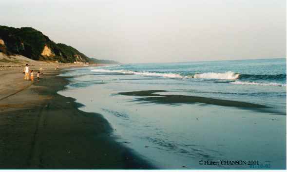 Earthquake related disasters
Earthquake
engineering
An earthquake is a violent earth tremor. (References : USGS Earthquake Hazards Program,
Various
links, Earthquake
locator)
ee1- Sanjusangen-do temple
(AD 798/last rebuilt 1633), Kyoto, Japan. Earthquake resistant building,
constructed on timber piles set in a pit filled with superposed
layers of sand and clay.
Tsunami
A tsunami is a long-period wave generated by ocean
bottom motion during an earthquake. (Tsunami is Japanese word meaning
"harbour wave". A tsunami is also called seismic sea wave. It is
sometimes incorrectly termed "tidal wave" but the process is not
related to the tides.) Occasionally a tsunami might be caused by
another earth movement (e.g. underwater landslide, volcanic activity).
(A related case is the impulse wave generated by rockfalls,
landslides, ice falls, glacier breakup or snow avalanches in lakes and
man-made reservoirs. Some impulse waves might be induced by
earthquake-generated falls.) The tsunami wave length is typically
about 200 to 350 km and the tsunami behaves as a shallow water wave,
even in deep sea. Although the wave amplitude is moderate in the
middle of the ocean (e.g. 0.5 to 1 m), the tsunami wave slows down and
the wave height increases near the shoreline, with periods ranging
between 20 minutes and several hours typically. The wave runup height
might reach several metres above the natural sea level.
Relevant links: Pacific Tsunami
Warning Center {http://tsunami.gov/}
- Tsunami Pacific Museum {http://www.tsunami.org/}
- NOAA Tsunami website {http://www.tsunami.noaa.gov/}
- NOAA {http://www.noaa.org/} - Experimental Study of Tsunami Runup on
Dry and Wet Horizontal Coastlines (International
Journal
of the Tsunami Society, Science of Tsunami Hazards., Vol. 20,
No. 5, pp. 278-293 )- The
26 December 2004 Tsunami: a Hydraulic Engineering Phenomenon of
International Significance. First Comments (Jl
La Houille Blanche, 2005, No. 2, pp. 25-32).
ts1- Tsunami warning
signs in Japan. Photo No. 1 :
Tsunami warning sign post off Takatoyo beach, Enshunanda (Aichi
Prefecture) on 27 March 1999; note the surfers and fishermen
drawings. Photo No. 2 : the same
old warning sign on 7 November 2008. Photo
No. 3 : new tsunami warning sign on Takatoyo beach on 7 November
2008. Photo No. 4 : another type
of new tsunami warning sign in Aichi Prefecture on 22 November 2008
along the Enshu coastline. Photo No.
5: another type of new tsunami warning sign at Mutsure
fishing harbour (Aichi Prefecture) on 23 Nov. 2008. Photo
No. 6: another new tsunami warning sign at Magome River mouth
(Shizuoka Prefecture) on 27 Nov. 2008. Photo
No. 7: another new tsunami warning sign at the Tenryu River
mouth (Shizuoka Prefecture) on 27 Nov. 2008.
[Related : Calculating
the threat of tsunami]
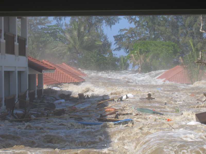 ts2- Tsunami
in
Indonesia on 26 December 2004 (Magnitude 9.0)
ts2- Tsunami
in
Indonesia on 26 December 2004 (Magnitude 9.0)
ts2.1 USGS Earthquake Hazards Program report {http://earthquake.usgs.gov/eqinthenews/2004/usslav/}
Preliminary
Earthquake
Report
U.S. Geological Survey, National Earthquake Information
Center
Magnitude 9.0
Date-Time Sunday, December 26, 2004
at 00:58:50 (UTC) - Coordinated Universal Time (Sunday, December 26,
2004 at 07:58:50 AM local time at epicenter)
Location 3.30N 95.78E
Depth 10.0
kilometers
Region OFF W COAST
OF NORTHERN SUMATRA
Reference 250 km (155 miles) SSE of
Banda Aceh, Sumatra, Indonesia - 320 km (200 miles) W of Medan,
Sumatra, Indonesia - 1260 km (780 miles) SSW of BANGKOK, Thailand -
1605 km (1000 miles) NW of JAKARTA, Java, Indonesia
Location Quality Error estimate:
horizontal +/- 9.3 km; depth fixed by location program
Source USGS NEIC (WDCS-D)
Report
on
31/12/04 : At least 79,900 people were killed by the earthquake
and tsunami in Indonesia. Tsunamis killed at least 24,600 people in
Sri Lanka, 10,000 in India, 1,830 in Thailand, 120 in Somalia, 90 in
Myanmar, 66 in Malaysia, 46 in Maldives, 10 in Tanzania, 2 in
Bangladesh, 1 in Seychelles and 1 in Kenya. About 12,000 people
throughout the region are still listed as missing. Tsunamis caused
damage in Madagascar and Mauritius and also occurred on Cocos Island
and Reunion. The tsunami crossed into the Pacific Ocean and was
recorded in New Zealand and along the west coast of South and North
America. The earthquake was felt (VIII) at Banda Aceh and (V) at
Medan, Sumatra and (II-IV) in parts of Bangladesh, India, Malaysia,
Maldives, Myanmar, Singapore, Sri Lanka and Thailand (Maps 1 & 2).
This is the fourth largest earthquake in the world since 1900 and is
the largest since the 1964 Prince William Sound, Alaska earthquake. Map
No.
1. Map
No.
2.
ts2.2 Preliminary comments on 5/01/2005 by Hubert
Chanson to River-List and Coastal_list, and
additional comments on 9/2/2005
"Based upon the images and videos that I saw since the
26/12/04, it seems that the tsunami wave runup had different
characteristics depending upon the locations and coastline shapes.
While it is impossible to generalise, I feel that a few trends
emerged.
In
Thailand,
videos showed an "explosive" process, with tsunami waves breaking near
the shore, and waters surging on the dry land. The surging waters
advanced on dry land at high speed (> 3 m/s) and the water level
increases from zero to more than 3 m (1 storey) in less than 2
minutes. Visually, the surging waters on dry land looked somehow like
a dam break wave. In Sri Lanka, there is very little video footage. (I
saw 2 videos only). But the photographic evidences suggest that the
tsunami waves rushed at a slower pace, than in Thailand, and that most
damage resulted from the flooding waters. As an anecdoct, this is
possibly the first time that a train is destroyed by a tsunami. In
Indonesia, both photographs evidence of damage, satellite photographs
of the devastation and a video suggests that the tsunami impact on the
coastline was very powerful, possibly explosive, followed by large
masses of waters and debris running up on the dry land. One video
suggests that the water depths exceeded 3-4 metres at Band Aceh in one
place. Note that the tsunami waves reached the coastlines at Banda
Aceh around 8:30 am local time, during ebb tide, and the rising tide
(tidal range ~ 1.2 m) may have contributed to further runup heights.
However a video at Leupung (Tim Palmer, ABC 5/1/05) showed very
extensive damage to the hillslopes. I personally experienced only once
such devastation. It was in the Reyran valley, downstream of the
Malpasset dam. (The 100 m Malpasset arch dam broke in 1959 when the
reservoir was full. More than 400 in Frejus and St Rapahel were
killed. Forensic investigations showed that the dam break wave was
about 40 m high at 340 m downstream of the dam site, and still 7 m
high 9 km downstream of the dam site !)� The video footage at Leupung
suggest a very significant wave runup height, possibly higher than 15
m". (5/01/2005)
"The hydraulic engineering community has been relatively slow to
comprehend the magnitude of the event, to accept its implications and
to do something about it. For example: on 26/27/28 Dec. 2004,
most tsunami runup models predicted large runup heights in Bangladesh
(eg up to 4-8 m) which never materialised. These same models predicted
runup heights of 10 m in Indonesia only. Clearly current expertise is
grossly inadequate, and we (academics, researchers and professionals)
are to blame !
I feel that we (academics, researchers and professionals) could
ask himself/herself : what have I contributed ? what can I do ? how
can I improve current expertise in tsunami modelling or mitigation ? I
believe strongly that we have professional duties and we must face our
responsibility for the present lack of expertise. Herein, "we" means
every academic, professional, researcher including you and I ."
(9/02/2005)
ts2.3
Video animation of the tsunami propagation prediction by the USGS -
Credit NOAA (Quicktime movies). Movie
No. 1: preliminary tsunami prediction in Indian Ocean. Movie
No. 2: tsunami prediction in Indian Ocean. Movie
No. 3 : complete preditions.
 ts2.4 NOOA
Compilation of report, data and information {http://www.pmel.noaa.gov/tsunami/sumatra20041226.html}
ts2.4 NOOA
Compilation of report, data and information {http://www.pmel.noaa.gov/tsunami/sumatra20041226.html}
ts2.5 Engineering report by the French Atomic Energy Commission {http://www-dase.cea.fr/actu/dossiers_scientifiques/2004-12-26/index.html}
(in French).
ts2.6 The December 26, 2004 Earthquake Tsunami
Disaster of Indian Ocean by Research Group on
The December 26, 2004 Earthquake Tsunami Disaster of Indian Ocean {http://www.drs.dpri.kyoto-u.ac.jp/sumatra/index-e.html}
ts2.7 NASA Earth Observatory photographs of the
devastated coatal zones {http://earthobservatory.nasa.gov/NaturalHazards/shownh.php3?img_id=12643}
- See also "Other Images for this Event".
ts2.8 Series of video from
"Waveofdestruction.org" {http://www.waveofdestruction.org/}
ts2.9 Wikipedia, the free encyclopedia 2004 Indian Ocean earthquake.
Comprehensive report {http://en.wikipedia.org/wiki/2004_Indian_Ocean_earthquake}
ts2.10 Japanese Website on Tsunami Research {http://www.drs.dpri.kyoto-u.ac.jp/sumatra/index-e.html}.
Include
links on the tsunami {http://www.drs.dpri.kyoto-u.ac.jp/sumatra/index-e.html},
a
timetable of the tsunami propagation{http://staff.aist.go.jp/kenji.satake/Sumatra-E.html}
and tidal gauge data {http://www.drs.dpri.kyoto-u.ac.jp/sumatra/index-e.html#tn}.
ts2.11 Tsunami propagation and observations on Queensland coast,
Australia {http://www.epa.qld.gov.au/publications/p01500aa.pdf/Queensland_EPA_monitors_2004_Asian_Tsunami.pdf}.
ts2.12
Engineering survey at Phuket and report by a
Japanese-Thai research team led by DPRI Kyoto {http://www.drs.dpri.kyoto-u.ac.jp/sumatra/thailand/phuket_survey_e.html}
ts2.13 Second Engineering survey at Phuket and report by a Japanese-Thai research team led
by DPRI Kyoto {http://www.drs.dpri.kyoto-u.ac.jp/sumatra/thailand}
ts2.14 Report and photographs on tsunami damage
in Indonesia by Dr Jose Borrero, University of Southern California {http://www.usc.edu/dept/tsunamis/2005/tsunamis/041226_indianOcean/sumatra/sumatra.html}
ts2.15 Engineering Report on tsunami runup heights in Indonesia, by
the International Tsunami Information Center (ITIC) Team {http://www.eri.u-tokyo.ac.jp/namegaya/sumatera/surveylog/eindex.htm}.
ts2.16 Engineering report on tsunami runup heights around Galle, Sri
Lanka, by a Japanese team {http://www.drs.dpri.kyoto-u.ac.jp/sumatra/srilanka/galle_survey_e.html}
ts2.17 Engineering report on tsunmai runup heights around Southern
Part of Sri Lanka, by Yokohama National University {http://www.drs.dpri.kyoto-u.ac.jp/sumatra/SriLanka_survey_result/srilanka_survey_ynu_e.html}
ts2.18 Measurements made in Indonesia by Russian team field
survey - January 20-29, 2005 {http://tsun.sscc.ru/tsulab/20041226.htm}
and relevant information
Read "The 26 December
2004 Tsunami: a Hydraulic Engineering Phenomenon of International
Significance. First Comments." Jl
La Houille Blanche, 2005, No. 2, pp. 25-32 (ISSN 0018-6368) (Download PDF
file).
Photographs
ts2.51 Reunion
island (ile de la Reunion) : photographs suggested a small vertical
runup. Photo
1 :
photograph taken between 13h30 and 14h00 at Port de St Pierre on 26
Dec. 2004 by Axou. Photo 2
: St Pierre beach (Plage de St Pierre) around 13h30 after the first
tsunami wave on 26 Dec. 2004 (photograph by Axou); note the marks
left by the wave runup on the beach.
ts2.52 Photographs at Khao Lak (or Kaoh Lak), Thailand by
John M. THOMPSON {http://www.sonomacountylaw.com/tsunami/index.htm}.
Photo No. 1 : seconds before the
tsunami waves hit the land, at 10:26 local time (Courtesy of John M.
THOMPSON). Photo No. 2 : tsunami waters sweeping through the Seagull Andaman Resort,
at 10:28 local time (Courtesy of John M. THOMPSON). Photo
No. 3 : waters receeding through
the resort at 10:32 local time (Courtesy of John M. THOMPSON). Photo No. 4 : debris during water
receeding, around 10:32 local time (Courtesy of John M. THOMPSON). Photo
No. 5 : almost two hours (around 12:00noon) after the
first tsunami wave struck (Courtesy of John M.
THOMPSON). Photo
No. 6 : Large bay where
there used to be only a small river (Courtesy of John M.
THOMPSON). See also NASA Earth Observatory
Images {http://earthobservatory.nasa.gov/NaturalHazards/natural_hazards_v2.php3?img_id=12648}
&{http://earthobservatory.nasa.gov/NaturalHazards/natural_hazards_v2.php3?img_id=12677}.
Space
Imaging pictures {http://www.spaceimaging.com/gallery/tsunami/default.htm#khaolak}.
ts2.53
Photographs
on
tsunami
damage in Indonesia by Dr Jose Borrero, University of Southern
California {http://www.usc.edu/dept/tsunamis/2005/tsunamis/041226_indianOcean/sumatra/sumatra.html}
tc2.54 Photographs of tsunmai damage around the Indian Ocean by Dr
Jose Borrero {http://www.usc.edu/dept/tsunamis/2005/tsunamis/041226_indianOcean/041226_indianOcean.html}
ts2.55 Photo / Image Database by Kenji Harada, DPRI University of
Kyoto - The December 26, 2004 Earthquake Tsunami Disaster of
Indian Ocean {http://www.drs.dpri.kyoto-u.ac.jp/sumatra/photo/?exec=SEARCH&m=s&q=kenji+harada}
ts2.56 Photographs from NASA Earth Observatory {http://earthobservatory.nasa.gov/NaturalHazards/shownh.php3?img_id=12643}
- See also "Other Images for this
Event".
ts2.57 Photographs of tsunami damage in Western Aceh by Russian team {http://tsun.sscc.ru/tsulab/20041226photos.htm}.
Taiwan Chi-Chi earthquake (21
Sept. 1999)
cc1- Failure of building
columns at the ground floor in Nantou (Photograph taken on
25-9-99, Courtesy of Ms YANG Soo-Zhen).
cc2- Overhanging roof
sections in Nantou (Photograph taken on 25-9-99, Courtesy of Ms
YANG Soo-Zhen).
cc3- Complete collapse
of a ground floor, in Nantou (Photograph taken on 25-9-99,
Courtesy of Ms YANG Soo-Zhen). Note the crushed cars on the left.
cc4- Damage to a school
building, in Nantou (Photograph taken on 25-9-99, Courtesy of Ms
YANG Soo-Zhen). Note that the walls connecting the columns
(ground floor) had some impact on the location of the column
failure (Comments by Mr W.H. BOYCE).
cc5- Building tilted
following failure of the ground floor, in Nantou (Photograph
taken on 25-9-99, Courtesy of Ms YANG Soo-Zhen).
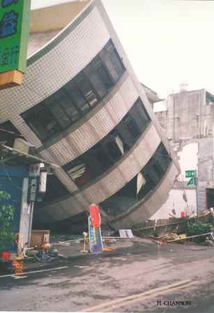 cc6- Building
tilted by quake. (Photograph taken on 25-9-99, Courtesy of Ms
YANG Soo-Zhen)
cc6- Building
tilted by quake. (Photograph taken on 25-9-99, Courtesy of Ms
YANG Soo-Zhen)
cc7- Collapse of the
ground floor, in Nantou (Photograph taken on 25-9-99, Courtesy
of Ms YANG Soo-Zhen). The column remains are testimony of the
failure.
cc8- Road damage in Nantou (Photograph taken on 25-9-99,
Courtesy of Ms YANG Soo-Zhen) - Photo
No. 1; Photo No. 2.
cc10 - Waterfall was
caused by an upward fault thrust downstream of Shih-Kang Dam.
The Bei-Fung bridge on the left was destroyed because one pier was
pushed about 7-m upwards by the fault (Courtesy of the Department of
Economics Affairs, Taiwan R.O.C., and Mr Shiang-Kueen HSU). (Basic
reference : HWANG 1999)
cc11- Shih-Kang dam
on the Ta-Chia river. Destruction of three spillway gates on the
right-side of Shih-Kang dam (Courtesy of the Department of Economics
Affairs, Taiwan R.O.C., and Mr Shiang-Kueen HSU). The detoured branch
of the Cher-Lung-Pu fault ran across the Northern end of the dam. The
South side of the fault raised the dam by 9.8 m and the North side by
2-m, and destroyed the Northern spillways and gates of the dam (Basic
reference : HWANG 1999, pp.
22-23).
cc12- Failed road span
and pier for the last spillway gate at Shih-Kang dam (Courtesy
of the Department of Economics Affairs, Taiwan R.O.C., and Mr
Shiang-Kueen HSU). (Basic reference : HWANG
1999)
More
information {http://www.rcep.dpri.kyoto-u.ac.jp/main/taiwan/index-E.html}.
More
links {http://www2.rcep.dpri.kyoto-u.ac.jp/~sato/taiwan/index.html},
{http://www.iris.washington.edu/DOCS/taiwan.htm}.
Aircrafts
and "Flying machines"
Airships
afm1- Airship at Archerfield,
Brisbane. Holden Airship at Archerfield on 19 Oct. 2006, around 3:00pm
before a storm coming from the South (dark clouds in backgrounds). Note
the digital TV screen (21.m by 9.1 m) on the left side (black screen
off). The airship model is a A-170 Lightship filled with 5 ML of Helium.
The airship is 54.3 m long and 16.8 m hig.Cruise Speed 74 km/h. Maximum
Speed 84 km/h. Power: Twin Lycoming IO-360-B1G6 with constant-speed
variable-pitch reversible propellers. Max rate of climb: 425 metres per
minute. Max rate of descent: 485 metres per minute.
Photo No 1 : view
on 19 Oct. 2006. Photo No. 2 :
view on 19 Oct. 2006. Photo
No. 3 : side view on 19 Oct. 2006; note
the television screen.
Helicopters
afm11- Seahawk of the
Taiwanese Navy in Hualien. Photo No.
1 : view from Hualien pebble beach on 22 Nov. 2006. Photo
No. 2 : view from Hualien pebble beach on
22 Nov. 2006.
"Flying machines"
afm21- Motorised parachute (Aerochute) off La Ville Pichard,
Pleneuf-Val-Andre on Sun. 11 Apr. 2004 around 15:00. Photo
No. 1: Take off.
afm22- Delta wing (Hand glider) in
Pleneuf-Val-Andre on Sun. 11 Apr. 2004 around 15:00. Photo
No. 1 : Hand glider above Le Verdelet. Photo
No. 2 : the same hand glider above La Ville Pichard.
afm23- Kite on the Val-Andre beach in April
2004. Photo No. 1: kite above the
beach at low tide.
Ships and sailing boats
safm1- Trimaran Stalaven,
skipped by Pascal
QUINTIN. Length: 15.2 m, width: 14.0 m, mast: 23.8 m high, sailing
surface: 125 m2 (285 m2 with spinnaker). Photo
No. 1 : Trimaran Stalaven off Plage du Val
André, France on 11 Oct. 2008 at high tide. Photo
No.
2 : Trimaran Stalaven behind la Grande
Jaune off Plage du Val André,
France on 11 Oct. 2008 at high tide. Photo
No.
3 : Trimaran Stalaven in front of Le
Verdelet off Plage du Val André,
France on 11 Oct. 2008 at high tide. Photo
No. 4 : Trimaran Stalaven in front of Port
de Piegu, Le Val André, France
on 11 Oct. 2008 at high tide. Photo No.
5 : Trimaran Stalaven in front of Le
Verdelet off Plage du Val André,
France on 11 Oct. 2008 at high tide. Photo
No.
6 : Trimaran Stalaven off Plage du Val
André, France on 11 Oct. 2008 at high tide.
More on the Baie
de Saint Brieuc, and the Atlantic
Wall
fortifications.
safm2- La Pauline, a former
pilot ship for the Port de Dahouet. Photo
No. 1 : La Pauline off Plage du Val
André, France on 11 Oct. 2008 at high tide. Photo
No. 2 : La Pauline off
Plage du Val André, France on
11 Oct. 2008 at high tide.
C1 - Roman Perge (Turkey) - Photo
No. 1 : Water channel from the Northern monumental Nymphaeum to
the city gate and Hellenistic towers, looking downstream (2nd century
AD) (Courtesy of M. MENGEL and D. MURPHY, Oct. 1997).
C2- Angkor, Cambodia - Photo
No.
1 : moat at Bantay-Srei in Dec. 2001 (Courtesy of Mr and Mrs
CHANSON). Photo No. 2 : Neak-Pean,
square basin in Dec. 2001 (Courtesy of Mr and Mrs CHANSON). Photo
No. 3 : human face of the Gange river at Neak-Oean in Dec. 2001
(Courtesy of Mr and Mrs CHANSON).
C3- La Grande Cascade de Rueil (France, 1638) - Photo
No. 1 : Gravure of the cascade (Courtesy of the Musée de
l'Histoire de Rueil-Malmaison, Mrs KALENITCHENKO and Mrs D.
HELOT-LÉCROART).
The château of Rueil was built and designed by
Jacques LEMERCIER in 1625. Cardinal de Richelieu bought the château in
1631. The complete garden included a Great Cascade (~ 30 steps) designed
by Thomas FRANCINI and completed around 1638 (HELOT-LÉCROART 1985). The
cascade was at the end of the Grande Allée (PLUMPTRE 1993). MOSSER and
TEYSSOT (1991) suggested that Rueil's cascade and gardens were inspired
by Frascati (Villa Aldobrandini ?). It is believed that the Cascade of
Rueil inspirated the cascades of Versailles, St-Cloud and Sceaux
(CHANSON 1998). The cascade was replaced by a green lawn in 1720. The
17-th century formal garden does not exist any longer. Imperatrice
Joséphine stayed in Rueil and orderd a remodelling of the park.
Note : Thomas FRANCINI was an Italian landscape architect.
He went to France working for King Henri IV with his brothers Alexandre
and Camille. He was "Superintendant of the Waters and Fountains of
France" under Henri IV. His son François FRANCINE changed the family
name to FRANCINE. François and his brother Pierre continued the work of
their father Thomas, Pierre working as deputy of François.
C4- Bassin de Latone, Château de Versailles (France, 1670)
- Photo No. 1 : Grandes eaux in
June 1998
Designed in 1670 by G. MARSY (French sculptor, 1625-1681),
the statue of Latone (mother of the Gods Apollon and Diane) is in
marble. The fountain and statue represents Latone with her children.
While drinking, she was insulted by the peasants of Lycie : she asked
Jupiter to punish the peasants and to transform them in aquatic animals.
The lower levels of the fountain represent some of the aquatic animals.
The Bassin de Latone is located in the Jardin du Château de Versailles,
between the Chateau and the Grand Canal.
C5 - Bosquet des Rocailles, Château de Versailles (France,
1683) - Photo No. 1 : panoramic
view. Photo No. 2 : water jets and
cascading waters. Photo No. 3 :
details (Photographs taken during the Grandes Eaux on 20 June 1998).
Le Bosquet des Rocailles (or Bosquet de la Salle de Bal)
was built between 1680 and 1683 by J. MANSART in the gardens of the
Chateau de Versailles (France). The sculptures were by Pierre LEGROS
(1629-1714) and Benoît MASSOU (1627-1684). The cascade comprises : 5
8-steps fountains, 8 7-steps fountains, and 4 4-steps fountains. The
Bosquet itself was designed by LENOTRE in 1680. The scene was modified
in 1690 and flowers were introduced in 1691.
C6- L'escalier d'eau des jardins du Château du
Touvet, Le Touvet (Isère, France, 1770) - Photo
No. 1 : looking downstream at the water staircase with the
Belledonne mountains in background (Courtesy of Mr O de Quinsonas). Photo No. 2 : detail of the water
staircase (Courtesy of Mr F. BOTTON). Photo
No. 3 : General view of the water staircases in 2002
(copyrights Jardins du Touvet). Photo
No. 4 : Upper water staircases in 2002 (copyrights Jardins du
Touvet).
The first "château" was built during the 13-th century.
The present chateau was built in 15th century. Between 1753 and 1770,
the Comte Pierre de MARCIEU re-designed the garden, including a new
water staircase. The staircase is very pretty. The staircase is divided
in 5 successive series of steps (pooled steps with rounded crest). From
the top to the bottom : a steep cascade (> 8 steps), a second
steep cascade (9 steps), followed by a flat series of drops (6 steps,
slope ~ 6 deg.), a steep cascade (10 steps, slope ~ 27 deg.), and
another steep cascade (8 steps). Visit the website of the Château du
Touvet : {http://www.touvet.com/}.
C7 - Franklin D. Roosevelt memorial (Washington DC, USA) -
Photo No. 1 : stepped cascade in June
1998.
C8- Hong Kong Park (Hong Kong) - Photo
No. 1 : water staircase in Sept. 1994.
C9- Jardins du Trocadero, Paris, France (in Aug. 1996). Photo No. 1 : water jets and Eiffel
tower in background (Courtesy of Mr and Mrs CHANSON). Photo
No. 2 : Water cannons in action, with Eiffel tower in background
(Courtesy of Mr and Mrs CHANSON).
C10- Artifical cascade
at the bottom of the cable car at Mutianyu Great Wall (China) on 19
Sept. 2001.
C11- Non Hoi Park, Toyohashi (Japan) - Artifical
staircase cascade on 13 Oct. 2001. Waters
jets and cascades on 13 Oct. 2001.
C12- Step-pooled cascade
in the Floral Park at Hama-matsu, Japan on 9 March 1999. It acts as a
pool-stepped spillway of an aesthetic pond. The photograph was taken in
winter when the cascade was dry.
C13- Victoria Point Cascades on 16
Jan. 2003, Water fountain with slate arrangement, next to
h Environmental park.
C14- Hualien city fountain, East coast of Taiwan. Photo
No. 1 : fountain on 23 Nov. 2006. Photo
No. 2 : details of the water jets and splashing on 23 Nov. 2006
(shutter speed: 1/80 s).
Learn more about the Formal
Water Garden
.... Natural cascades and
waterfalls : Click Here.
Artifical river system, fishway and fish pas : Click
Here.
e1- Stepped spillway and chute flow
Flat stepped channel flow : Photo
No. 1 : nappe flow down a 3.4 degree slope (h=0.14 m) - flow from
bottom to top [Ref.: CHANSON & TOOMBES
1998, ICMF'98]; Photo No. 2 :
transition flow down a 3.4 degree slope (h=0.07 m) for dc/h=1.2, looking
downstream (April 2000). Read "Energy
Dissipation
and Air Entrainment in a Stepped Storm Waterway: an Experimental Study." Jl of Irrigation and Drainage Engrg., ASCE, 2002,
Vol. 128, No. 5, pp. 305-315 (Download PDF
File).
Skimming
flow down a 50 degree slope (h=20mm). The inception point of air
entrainment is clearly visible.
More
Photographs of stepped chute flows
...
e2- Air entrainment at a vertical supported jet
Individual
bubble entrainment at a vertical supported jet [Ref.: CUMMINGS
& CHANSON 1999]. Low-speed air bubble entraiment. Elongated
air cavity formation & entrainment of bubbles. Cavity and scaling
located 45-mm towards the camera from the jet centre line. Jet impact
flow conditions : V = 1.20 m/s, Tu = 1.08 %, d = 8.0 mm, Lj =
34mm - Video shutter speed : 1.0 ms; Frame interval : 20 ms.
Strong
air entrainment : V1 = 6.14 m/s, x1 = 0.090 m, probe position :
x-x1 = 0.10 m [Ref.: BRATTBERG and
CHANSON 1998].
More
on Air
entrainment in the developing flow region of two-dimensional
plunging jets ...
e3- Air bubble entrainment at a circular
vertical plunging jets
Experiments at the
University of Queensland (H. CHANSON 1998), flow from top to
bottom (Circular jet, V1 = 3.3 m/s, do = 25 mm) with freshwater
Experiments at Toyohashi University of Technology with
freshwater : Photo No. 1 : air
entrainment at a 12.5 mm diameter plunging jet (V1 = 2 m/s). Photo
No. 2 : air entrainment at a 6.83 mm diameter jet (V1 = 2.1 m/s).
Experiments at Toyohashi University of Technology with
seawater : Photo No. 1 : air bubble
entrainment at a 12.5 mm diameter plunging jet (x1 = 0.05 m, V1 = 2.5
m/s). Photo No. 2 : same flow
conditions, high shutter speed (1/1,000 s). Photo
No. 3 : seawater collection on 25 Oct. 2001. Photo
No. 4 : seawater collection and checking on 25 Oct. 2001.
Read "Bubble
Entrainment
and Dispersion in Plunging Jet Flows: Freshwater versus Seawater".
More
on Acoustic
characteristics of air entrainment at plunging jet ...
e5- Unsteady orifice experiment (two-dimensional orifice
70-mm*750-mm) : initial "bursting" flow,
free-falling nappe (front view, side view), Toyohashi University of
Technology [Ref.: CHANSON et al. 2002,
Jl of Hyd. Res.]
e6- Effect of air
bubble entrainment by plunging breakers on long-period waves. Photo
No. 1, Photo No. 2: views of
the unsteady plunging jet. Underwater views shorty after impingement : t = 0.3 sec., t
= 0.4 sec., t = 0.5 sec., t = 0.7 sec..Advancing undular
bore 10-m downstream of plunging jet (propagation from left to
right).
e7- Undular hydraulic jump looking downstream (Fr=1.2) and sideview (Fr=1.6)
(H. CHANSON Apr. 1993)
e8- Circular hydraulic
jump in a sink (Courtesy of Ph. BELLEUDY)
e9- Self-aeration on spillway chutes. Photo
No. 1 : self-aeration at Chinchilla weir on 8 Nov. 1997 during low
overflow (Weir height: 14 m, Crest length: 410m, Spillway capacity: 850
m3/s. More information : CHANSON,
Butterworth-Heinemann, 1999, pp. 417-421 & 316.) The point of
inception is visible near the upstream end of the chute. Note the light
brown colour of the flow, caused by the mixing of air bubbles and
sediment in the overflow.
More
about Air entrainment on chute spillways
...
e10- Double-tip
and single-tip conductivity (resistivity) probes developed at the
University of Queensland (CHANSON
1997). The 2-tip probe sensor has a 25 micron meter diamter. The
single-tip probe sensore has a 0.35-mm diameter. (Download
a report as PDF files : Part 1 and
Part 2) [Ref.: CHANSON
2002, Jl Hyd. Engrg.]
e11- Spillway aeration device model. Photo
No. 1 : 1/15 scale model of the Clyde dam spillway aeration
device; flow conditions : Fr = 6.5, V=5.8 m/s, d =85 mm.
More
about spillway aeration devices ...
Read "A Study of Air Entrainment and Aeration Devices on a Spillway
Model".
e12- Tainan Hydraulics Laboratory (Taiwan) - Photo
No. 1 : wave breaking on submerged breakwater blocks in the 300-m
long, 5-m deep canal (25 Sept. 2001).
e4- Air
entrainment
in a Roman dropshaft model (H. CHANSON 1998), flow from the top
left to the right. Note the downstream channel and the deep shaft. The
geometry is well-suited to maximise air bubble entrainment and gas
transfer in the shaft (e.g. re-oxygenation). [Ref.: CHANSON
2000,
Am Jl Archaeology, CHANSON
2002,
Jl of Hyd. Res.]
e13- Dropshaft hydraulics
Roman dropshaft in operation : Recret model (Aug. 1998) [Ref.: CHANSON 2000, Am Jl Archaeology, CHANSON 2002, Jl of Hyd. Res.]
Regime
R1 : the usual operation mode in Roman aqueduct (photo dc/h
=
0.06); Regime R2 : high
risks of erosion and damage at the intake of downstream conduit (photo
dc/h = 0.12); Regime R3
: at large flow rates, usual operation in modern sewer dropshaft
(photo dc/h = 0.22)
Roman dropshaft in operation : Valdepuentes
model (90-degree angled outlet) (Aug. 1999) [Ref.: CHANSON
2000,
Am Jl Archaeology, CHANSON
2002, Jl of Hyd. Res.]
Full scale hydraulic model of Roman
dropshaft. Drop in invert elevation: 1.7 m, pool depth: 1 m, shaft
dimensions: 0.75 m by 0.76 m, flow rates: 5 to 70 L/s (CHANSON
2004, Jl Irrigation & Drainage Engrg.). Regime
R1 : photograph for Q = 7.6 L/s (July 2002); Regime
R3 : photograph for Q = 67 L/s (Aug. 2002).
e14- Flow
past an orifice and a Venturi. Flow visualisation with a
smoke generator at the University of Queensland. Photo
No. 1: general view of the smoke general with the orifice and
Venturi models inside. Photo No.
2: turbulent flow visualisation; flow from bottom to top, with
the orifice model on the left and Venturi model on the right (shutter
speed: 1/80 s). Photo No. 3:
flow from bottom to top (shutter speed: 1/6 s). Photo No.4: turbulent flow
motion (shutter speed: 1/80s); note the flow separation downstream of
the orifice (left, top).
e-5 Fish passage in box culverts. Photo
No. 1: Juvenile Silver perch (Bidyanus bidyanus) swimming
upstream in a 12 m long 0.5 m wide rectangular channel equipped with
very rough invert and left sidewall. Photo
No. 2: Juvenile Silver perch (Bidyanus bidyanus) swimming
in the stagnation zone upstream of a small triangular baffle in a 12 m
long 0.5 m wide rectangular channel.
Teaching experiments and projects
te1- Hele-Shaw cell experiments
(1) Flow past a Rankine body,
where the green dye injected at the source does not mix with the red
dye injected in the uniform flow (flow from left to rigth). (2) Flow
past a thick rounded plate perpendicular to the flow (flow from
right to left). (3) Flow past a thick
rounded foil with 15% camber perpendicular to the flow (flow
from right to left)
(4) CIVL4160 Advanced Fluid Mechanics Student Group 1 looking at Hele-Shaw
cell apparatus with dye injection, model M3 (15% camber) with
zero angle of incidence on 26/04/2005
te2- Wind tunnel projects
2003 CIVL4160 wind tunnel projects: (1) Inflow conditions
: screens & grids and carpet
floor. (2) Model M1 : straight building with rounded edge and flat roof.
Photo No. 1: model standing in the
atmospheric boundary layer wind tunnel. (3) Model M2 : circular arc
building with 5% camber: Photo No. 1 :
model being installed on the turning table. (4) Model M3 : circular arc
building with 15% camber. Photo No. 1
: models M2 and M3 side by side.
2005 CIVL4160 wind tunnel projects: (Photo
No. 1) Group 2 students in wind tunnel installing the hot-wire
upstream of the building model M3 on 27/04/2005. Photo
No. 3 : Group 3 students in wind tunnel with building model M2 in
background on 28/04/2005. Photo No. 4
: Group 4 students checking pressure tappings on building model M1 on
29/04/2005.
2006 CIVL4160 Atmospheric Boundary Layer Wind Tunnel Project (Cyclonic
Wind Loads on Buildings). Photo No. 1
: Group 1 student porject with building model M3; installation of the
hotwire anemometer upstream of the building model. Photo
No. 2 : Group 2 students in the wind tunnel. Photo
No. 3 : Group 3 students installing the hot wire upstream of
building model M2. Photo No. 4 :
Group 4 students in the control room of the wind tunnel.
2007 CIVL4160/7160 Atmospheric Boundary Layer
Wind Tunnel Project (Cyclonic Wind Loads on Buildings). Photo
1.1 : Installation of the hot-wire probe above the rought
turbulent boundary layer experiment (Group 1). Photo
1.2 : Group 1 students preparing the building model M3 in hte wind
tunnel, looking downstream at the turn table and building model. Photo
2.1 : Group 2 students inspecting the rough turbulent boundary
layer experimental setup. Photo 2.2
: Hot-wire probe above the rough boundary layer experiment with some
Group 2 students in the control room in the background. Photo
3.1 : Group 3 students inspecting the wind tunnel equipment and
instrumentation. Photo 3.2 :
Rough boundary layer experiment setup with wind direction from right ro
left (Group 3). Photo 4.1 : Group
4 students preparing the rough boundary layer experiment. Photo
4.2 : Final instructions before the start of the experiment (Group
4). Photo 5.1 : Group 5 student
testing the wind flow (V ~ 16 m/s) in the wind tunnel (flow direction
from right to left). Photo 5.2 :
Group 5 students setting up the rough turbulent boundary layer
experiment. Photo 6.1 : Group 6
students in the wind tunnel control room. Photo
6.2 : Groud 6 students conducting hot-wire measurements from the
wind tunel control room.
2013 CIVL4160/7160 Wind tunnel project. Photo No.
2013.1: Group No. 1 students using in the wind tunnel facility. Photo No.
2013.2: Group No. 2 students using in the wind tunnel facility. Photo No.
2013.3: Group No. 3 students using in the wind tunnel facility. Photo No.
2013.4: Group No. 4 students using in the wind tunnel facility. Photo No.
2013.5: Group No. 5 students using in the wind tunnel facility. Photo No.
2013.6: Group No. 6 students using in the wind tunnel facility.
Student field works and studies
ft1- Hydrodynamics, water quality and biology in a
small estuary
(1) Field works on Friday 4 April 2003
Photo No. 11 : Group 1 on Fri 4 Apr
2003 around 7:30am. Photo No. 12 :
Group 1 on Fri 4 Apr 2003 around 12:00noon. Photo
No. 13 : Group 2 on Fri 4 Apr 2003 around 8:30am. Photo
No. 14 : Group 2 on Fri 4 Apr 2003 around 2:30pm. Photo
No. 15 : ADV velocimeter and YSI probe mounted 50 cm beneath the
free-surface on Fri 4 Apr 2003 around 10:00am. Photo
No. 16 : Group 3 on Fri 4 April 2003 around 11:00am. Photo
No. 17 : Group 3 on Fri 4 Apr 2003. Photo
No. 18 : Group 4 on Fri 4 April 2003 at 7:02am. Photo
No. 19 : Group 4 on Fri 4 Apr 2003 around 10:30am. Photo
No. 20 : Qld EPA boat conducting a vertical profile at Site 3 on
Fri 4 Apr 2003 around 11:00am. Photo No.
21 : Koala next to Site 1 on Fri 4 Apr 2003 around 5:00pm. Photo
No. 50 : Students and EPA boat at Site 2 around the middle of the
day (Courtesy of CIVL4140 Student Group 2). Photo
No. 51 : water quality observations at Site 2 (Courtesy of
CIVL4140 Student Group 2). Photo No. 52
: bird watching at Site 2 (Courtesy of CIVL4140 Student Group 2). Photo
No. 53 : fish dip netting at Site 2 (Courtesy of CIVL4140 Student
Group 2). Photo No. 54 : dissolved
oxygen testing at Site 2 (Courtesy of CIVL4140 Student Group 2). Photo
No. 55 : measurement preparation on the bank (Courtesy of CIVL4140
Student Group 2). Photo No. 60
: Students at Site 1 discussing with Waterwatch people (Courtesy of
CIVL4140 Student Group 3). Photo No. 61
: surface slick at Site 3 durign the flood flow (Courtesy of CIVL4140
Student Group 3). Photo No. 62 : Low
tide at Site 3, note bank erosion (right bank) (Courtesy of CIVL4140
Student Group 3). Photo No. 63 : Site
3 students during the afternoon (Courtesy of CIVL4140 Student Group 3).
Photo No. 70 : Upstream snag at Site
4 (Platypus pool) (Courtesy of CIVL4140 Student Group 4). Photo
No. 71 : Group work at Site 4 (Courtesy of CIVL4140 Student Group
4). Photo
No.
72 : student fishing at Site 4 (Courtesy of CIVL4140 Student Group
4). Photo No. 73 : fishing at Site 4
in front of ECCLA people (Courtesy of CIVL4140 Student Group 4). Photo
No. 74 : students at Site 4 (Courtesy of CIVL4140 Student Group
4).
(2) Field works on Thursday 2 September 2004
Site 1 : Photo No. 1.1 :Site 1
students around 7:15 am. Photo No. 1.2
: Site 1 around 12:00 noon at high tide. Photo
No. 1.3 : Site 1 activity around 6:30am. Site 2 : Photo
No.
2.1 : Site 2 students around 7:15 am. Photo
No. 2.2 : Site 2 activties around 11:00 am. Site 3 : Photo
No. 3.1 : Site 3 student activity around 6:45 am. Photo
No. 3.2 : Site around 16:30, with the EPA taking physico-chemical
readings mid-stream. Photo No. 3.3
: students around 13:00. Wildlife : Photo
No. 1 : Female koala next to Site 1 on 2 September 2004 around
8:40am. Overseas visitors: Photo No.1
: Professor Shin-ichi AOKI, Toyohashi University of Technology (Japan)
ft2- Sediment
processes and reservoir sedimentation
(1) Field study on 4 September 2002
Korrumbyn Creek dam (Murwillumbah NSW, Australia 1917). Photo
No. 1 : View from downstream on 25 April 1997. Photo
No. 2 : downstream view of the pipeline intake in April 1997. Photo No. 3 : Korrumbyn Creek
downstream of Korrumbyn Creek dam on 18 Aug. 2002. Note the huge bed
load material. Photo No. 4 :
Fully-silted reservoir with the dam wall in the background, on 17 Aug.
2002. Photo No. 5 : Bed load
material in the delta (upstream end) of the fully-silted reservoir on
17 Aug. 2002. Photo No. 6 : dam
wall view from the road on 17 Aug. 2002. Before June 2001, the dam
wall was not visible from the road, although the abutment is less than
10 m from the bitumen. Major floods in May/June 2001 flattened the
sub-tropical rainforest occupying the reservoir. Photo
No. 7 : Mount Warning on 18 Aug. 2002. The climb takes about 4
hours. Read the history of the dam: download PDF
file. More about Extreme reservoir
siltation ...
Field study: Photo
No. 8 : Korrumbyn Creek, looking downstrream during student
field trip on 4 Sept. 2002. Photo No.
9 : Korrumbyn Creek dam during student field trip on 4 Sept.
2002. Photo No. 10 : Korrumbyn
Creek reservoir, looking upstream during student field trip on 4 Sept.
2002.
ft3- Flood
plain
modelling and culvert design
(1) Field study on 13 May 2002
Photo No. 1 : Inlet of a MEL
culvert along Norman Creek underneath Ridge Street, Brisbane (QLD,
Australia). Note the handrail along the bicycle/footpath passing in
one cell. MEL culvert No. MEL-C-3 (CHANSON
1999, pp. 421-430). Design discharge : 220 m3/s, 7
cells of 2-m width each. View of the
inlet during a field trip with students in Aug. 2000. Culvert
outlet during field trip with students in Aug. 2001 (Courtesy of
Mr A.K. ABDULLAH SANI). Outlet
viewed from downstream on 13 May 2002 (Courtesy of C. HINTON). Inlet
operationOutlet
operation on 31 Dec. 2001 after a rainstorm (Q ~ 60-70 m3/s). Approach flood plain , Inlet
and Downstream flood plain during
CIVL4510 student survey on 13 May 2002.
Photo No. 2 : Outlet and barrel of
a MEL waterway along Norman Creek, under the South-East freeway and
parallel to Ridge St (Brisbane QLD, Australia). Looking upstream. MEL
waterway No. MEL-W-1 (CHANSON 1999,
pp. 421-430). Design discharge : 200 m3/s, Barrel width :
10 m. Outlet operation (view from
downstream) on 31 Dec. 2001 after a rainstorm (Q ~ 60-70 m3/s). Field
trip by CIVL4510 students (where are they?) on 13 May 2002. Photo No. 24: MEL water MEL-W-1
barrel in operation on 7 Nov. 2004, looking downstream; note the
standing wave flow; Photo No. 25:
inlet operation, view from right bank (MEL waterway (MEL-W-1) on 7
Nov. 2004); Photo No. 26: outlet
operation, looking upstream (MEL waterway (MEL-W-1) on 7 Nov. 2004).
Photo No. 4 : MEL culvert No. MEL-C-2 (CHANSON
1999, pp. 421-430). Design discharge : 220 m3/s. Located along
Norman Creek underneath SE Freeway parallel to Birdwood St, Brisbane
(Australia). Inlet, looking from
the left bank on 13 May 2002.
Photo No. 5 : MEL culvert No. MEL-C-X2 (CHANSON
1999), Ekibin Park, on Norman Creek. Design discharge : 220
m3/s. Built in 1971. Located underneath South-East Freeway. Inlet
survey during Field survey CIVL4510 on Mon 13 May 2002.
Photo No. 6 : MEL culvert No. MEL-C-4 (CHANSON
1999). Design discharge : ~220 m3/s. MEL culvert beneath the
Gateway motorway (Brisbane, Australia). Photo
No. 6a : inlet on 11 Sept. 2002 during CIVL3140 student field
trip. Photo No. 6b : inlet
wingwall on 11 Sept. 2002 during CIVL3140 student field trip.
Photo No. 7 : MEL culvert No. MEL-C-5 (CHANSON
1999). Design discharge : ~100 m3/s. MEL culvert beneath the
Gateway motorway (Brisbane, Australia). Photo
No. 7a : inlet on 11 Sept. 2002 during CIVL3140 student field
trip. Photo No. 7b : students in
inlet channel on 11 Sept. 2002 during CIVL3140 student field trip. Photo No. 7c : students at the
dowsntream end of the barrel on 11 Sept. 2002 during CIVL3140 student
field trip.
(2) Field works on 11 April 2005
Group 1 : students surveying the
Birdwood St MEL culvert inlet, looking upstream from the barrel. Group
2 : student discussion in the Ekibin MEL culvert inlet. Group
3 : survey preparation, downstream of the Ekibin MEL culvert
outlet. Group 4 : field work
preparation. Group 5 : survey of
the MEL waterway beneath the SE freeway. Group
6 : survey of the Ridge St MEL culvert inlet. Group
8 : flood plain survey downstream of Juliette St. Group
9 : student survey of Cornwall St culvert.
ft4- Hydraulic
design of spillway and stilling basin
Site visit with CIVL4120 Advanced hydraulics
students on 24 October 2014: Photo
No.11: general view of stepped spillway and stilling
basin. Photo No. 12:
stilling basin and turning veins leading to an ogee weir. Photo No. 13: stepped spillway
with 3.3 m high baffle blocks in the foreground. Photo
No. 14: details of baffle block. Photo
No. 15: engineering students discussing about the spillway
system next to a baffle block. Photo
No. 16: CIVL4120 students with Professor Chanson at the spillway
toe. Photo No. 17:
stepped spillway toe and stilling basin.
Read more on "Enhancing
Students' Motivation in the Undergraduate Teaching of Hydraulic
Engineering: the Role of Field Works" (2004 ASCE Jl
of Prof. Issues in Eng. Educ. and Practice, Vol. 130, No. 4,
pp. 259-268. "Should Field Works Be
Compulsory in Hydraulic Engineering Courses ?" IAHR
Newsletter, Vol. 22, No. 2, pp. 27-30.
Lecture
L1- Workshop on
Flow Characteristics around Hydraulic Structures and River Environment,
Nihon University, Tokyo (Nov. 1998) - Dr CHANSON showing the world's
oldest stepped spillway (BC 1,300) during the workshop.
L2- International Workshop on State of the Art in Hydraulic Engineering,
Bari, Italy, Feb. 2004. Photo No. 1:
lecture by Hubert CHANSON on tidal bores on
20 Feb. 2004. Photo No. 2 : lecture
on field work at Eprapah Creek by Hubert
CHANSON on 19 Feb. 2004. Photo No. 3
: some participants of the workshop on 17 Feb. 2004.
P1- Poster presentation
on "Study of Extreme Reservoir Siltation in Australia", Proc.
Water 99 Joint Congress, 25th Hydroogy & Water Res. Symp. and
2nd Intl Conf. Water Res. & Environ. Research, Brisbane,
Australia.
History of arch dams ...
{http://www.uq.edu.au/~e2hchans/arch_dam.html}
Timber crib weirs ...
{http://www.uq.edu.au/~e2hchans/tim_weir.html}
The
steel dams ... {http://www.uq.edu.au/~e2hchans/steel_da.html}
The
tidal bore of the Seine river ...
{http://www.uq.edu.au/~e2hchans/mascaret.html}
Engineering
failures ...
Extreme reservoir siltation
... {http://www.uq.edu.au/~e2hchans/res_silt.html}
Sabo check dams
... {http://www.uq.edu.au/~e2hchans/sabo.html}
Air entrainment on chute and
stepped spillways ...
{http://www.uq.edu.au/~e2hchans/self_aer.html}
Air
entraiment at a circular plunging jet: physical and acoustic
characteristics - Internet Database
{http://www.uq.edu.au/~e2hchans/bubble/}
Hydraulics of rubber dams ...
{http://www.uq.edu.au/~e2hchans/rubber.html}
Current
expertise
and experience on stepped channel flows
{http://www.uq.edu.au/~e2hchans/dpri/topic_2.html}
Embankment
overflow stepped spillways: earth dam spillways with precast
concrete blocks {http://www.uq.edu.au/~e2hchans/over_st.html}
Spillway
Aeration
Devices to prevent Cavitation Damage in high-head chutes
{http://www.uq.edu.au/~e2hchans/aer_dev.html}
Minimum
Energy Loss culverts and bridge waterways ...
{http://www.uq.edu.au/~e2hchans/mel_culv.html}
The
Minimum
Energy Loss (MEL) weir design: an overflow earthfill embankment
dam {http://www.uq.edu.au/~e2hchans/mel_weir.html}
The Formal Water Garden
.... {http://www.uq.edu.au/~e2hchans/wat_gard.html}
Whirlpools
... {http://www.uq.edu.au/~e2hchans/whirlpl.html}
License
This work is licensed under a Creative
Commons Attribution-NonCommercial 3.0 Unported License.
About Professor
Hubert CHANSON
Hubert CHANSON
is a Professor in Civil Engineering, Hydraulic Engineering and
Environmental Fluid Mechanics at the University
of Queensland, Australia. His research interests include design of
hydraulic structures, experimental investigations of two-phase flows,
applied hydrodynamics, hydraulic engineering, water quality modelling,
environmental fluid mechanics, estuarine processes and natural resources.
He has been an active consultant for both governmental agencies and
private organisations. His publication record includes over 850
international refereed papers and his work was cited over 4,300 times
(WoS) to 15,500 times (Google
Scholar) since 1990. His h-index is 34 (WoS), 38 (Scopus) and 61 (Google
Scholar), and he is ranked among the 150 most cited researchers in
civil engineering in Shanghais
Global Ranking of Academics. Hubert Chanson is the author of twenty
books, including "Hydraulic Design
of Stepped Cascades, Channels, Weirs and Spillways" (Pergamon,
1995), "Air Bubble Entrainment in
Free-Surface Turbulent Shear Flows" (Academic
Press, 1997), "The Hydraulics
of Open Channel Flow : An Introduction" (Butterworth-Heinemann,
1st edition 1999, 2nd
editon 2004), "The Hydraulics of
Stepped Chutes and Spillways" (Balkema,
2001), "Environmental
Hydraulics of Open Channel Flows" (Butterworth-Heinemann,
2004), "Tidal
Bores, Aegir, Eagre, Mascaret, Pororoca: Theory And Observations" (World
Scientific, 2011) and "Applied
Hydrodynamics:
an Introduction" (CRC
Press, 2014). He co-authored two further books "Fluid Mechanics for
Ecologists" (IPC Press, 2002) and "Fluid Mechanics for Ecologists.
Student Edition" (IPC, 2006). His
textbook "The Hydraulics of Open Channel Flows : An Introduction" has
already been translated into Spanish (McGraw-Hill
Interamericana) and Chinese (Hydrology Bureau of Yellow
River Conservancy Committee), and the second
edition was published in 2004. In 2003, the IAHR
presented him with the 13th Arthur Ippen Award
for outstanding achievements in hydraulic engineering. The American
Society of Civil Engineers, Environmental and Water Resources Institute
(ASCE-EWRI) presented him with the 2004 award for the Best Practice paper
in the Journal of Irrigation and Drainage Engineering ("Energy
Dissipation
and Air Entrainment in Stepped Storm Waterway" by Chanson and
Toombes 2002) and the 2018 Honorable Mention Paper Award for "Minimum Specific
Energy and Transcritical Flow in Unsteady Open-Channel Flow" by
Castro-Orgaz and Chanson (2016) in the ASCE Journal of Irrigation and
Drainage Engineering. The Institution of Civil Engineers (UK) presented
him the 2017 Baker. Medal. Hubert Chanson edited further several books : "Fluvial, Environmental and Coastal
Developments in Hydraulic Engineering" (Mossa, Yasuda & Chanson
2004, Balkema), "Hydraulics.
The
Next Wave" (Chanson & Macintosh 2004, Engineers
Australia), "Hydraulic
Structures:
a Challenge to Engineers and Researchers" (Matos & Chanson 2006,
The University of Queensland), "Experiences and
Challenges in Sewers: Measurements and Hydrodynamics" (Larrate &
Chanson 2008, The University of
Queensland), "Hydraulic
Structures:
Useful Water Harvesting Systems or Relics?" (Janssen & Chanson
2010, The University of Queensland),
"Balance
and Uncertainty: Water in a Changing World" (Valentine et al. 2011,
Engineers Australia), "Hydraulic
Structures and Society Engineering Challenges and Extremes"
(Chanson and Toombes 2014, University
of Queensland), "Energy
Dissipation
in Hydraulic Structures" (Chanson 2015, IAHR
Monograph, CRC Press). He chaired the Organisation of the 34th
IAHR World Congress held in Brisbane, Australia between 26 June and
1 July 2011. He chaired the Scientific Committee of the 5th IAHR
International Symposium on Hydraulic Structures held in Brisbane in
June 2014. He chairs the Organisation of the 22nd Australasian Fluid
Mechanics Conference in Brisbane, Australia on 6-10 December 2020.
His Internet home page is http://www.uq.edu.au/~e2hchans.
He also developed a gallery of photographs website {http://www.uq.edu.au/~e2hchans/photo.html}
that received more than 2,000 hits per month since inception.
If you find this Web page useful or have pictures of interest, you
are welcome to send
your comments and pictures.
This page was visited :144,294 times between
22-01-1999 and June 2012.
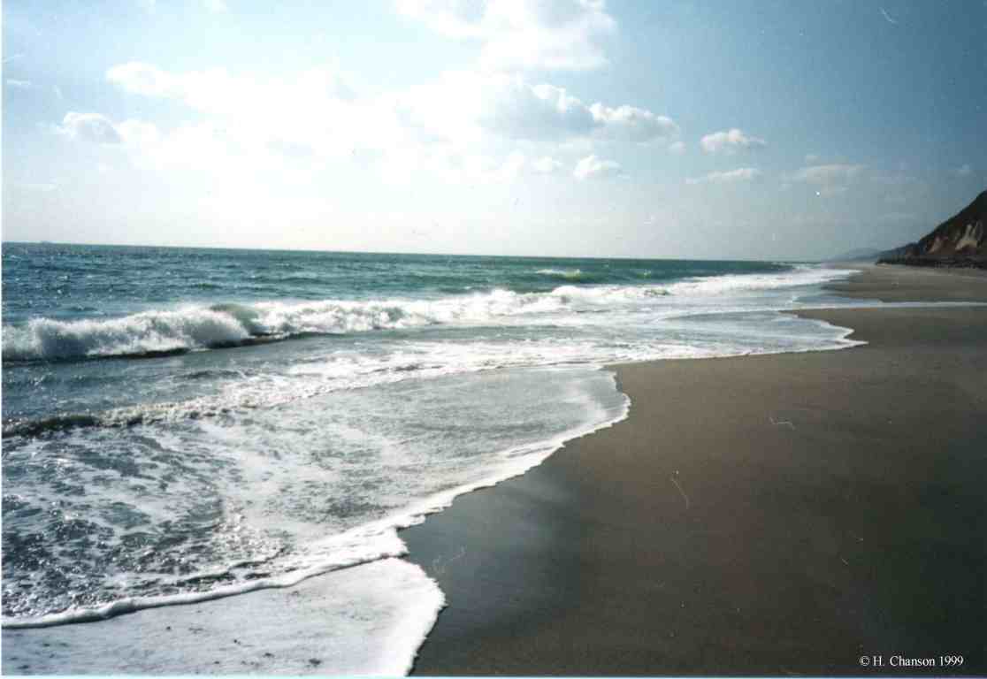 Coastlines
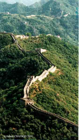 Civil Engineering
Structures
Civil Engineering
Structures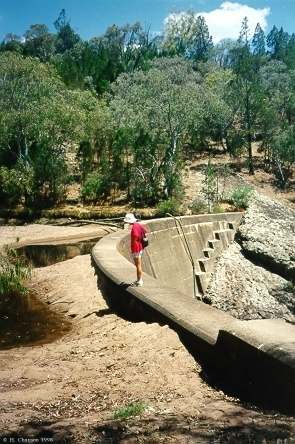 Engineering failures and
accidents of hydraulic and coastal structures
Engineering failures and
accidents of hydraulic and coastal structures ts2.4 NOOA
Compilation of report, data and information {http://www.pmel.noaa.gov/tsunami/sumatra20041226.html}
ts2.4 NOOA
Compilation of report, data and information {http://www.pmel.noaa.gov/tsunami/sumatra20041226.html}


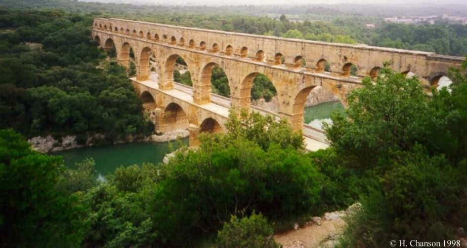
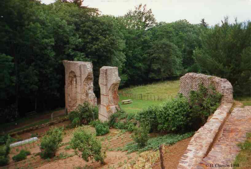
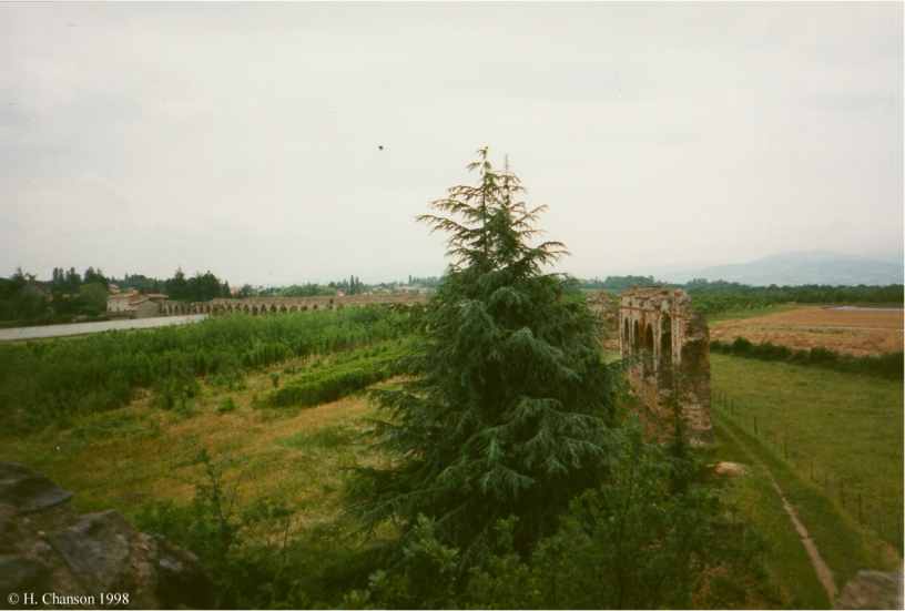
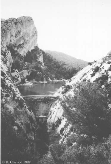
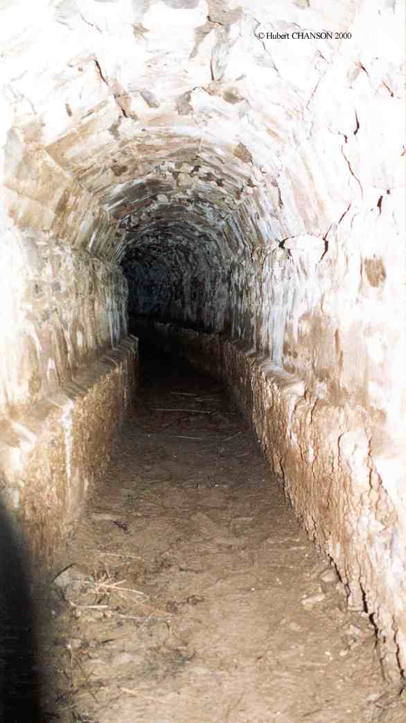
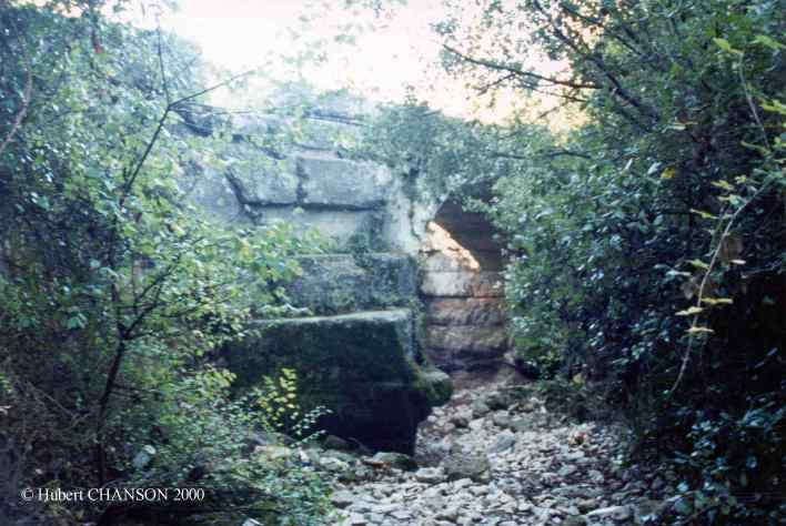
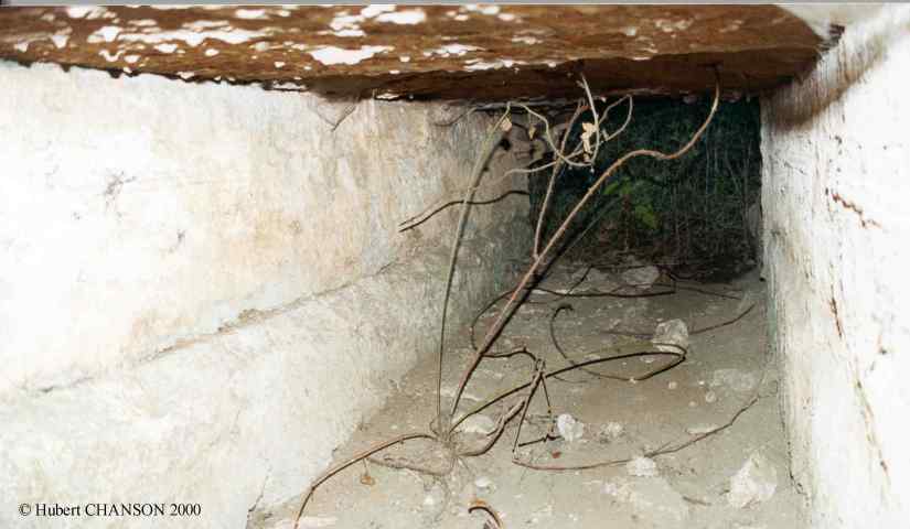
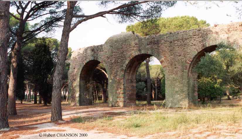
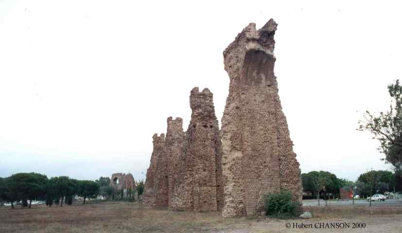
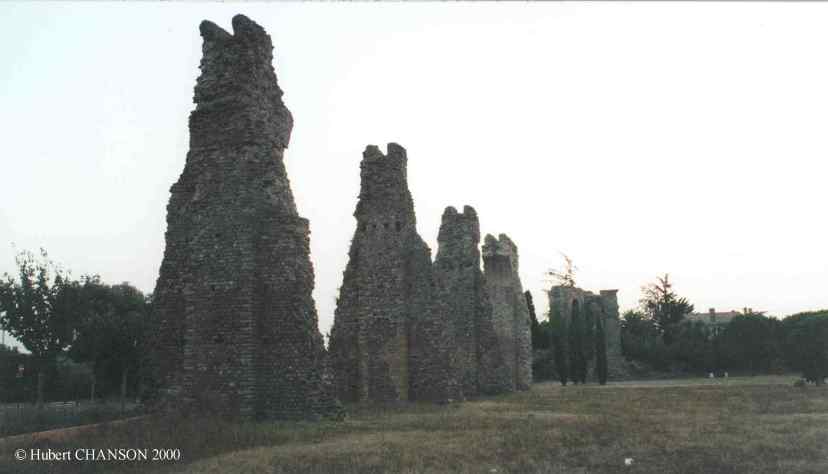
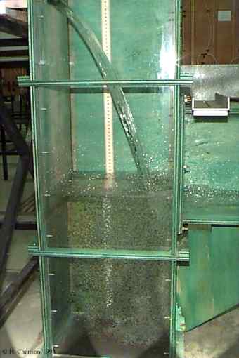
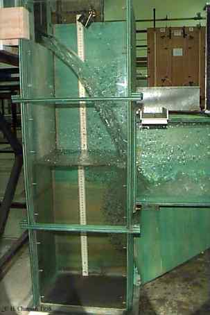
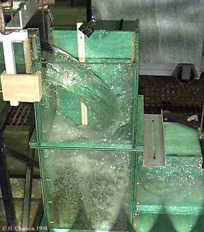
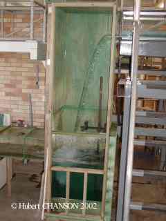
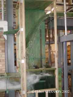
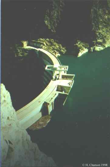
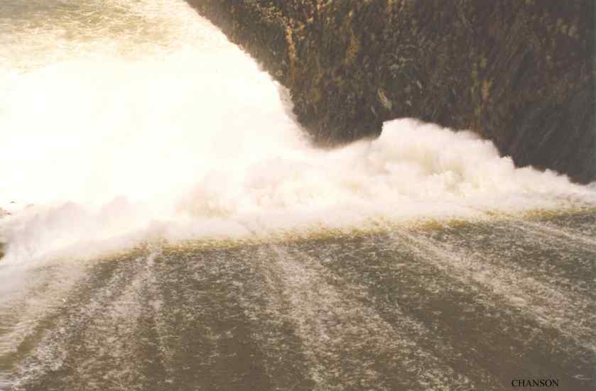
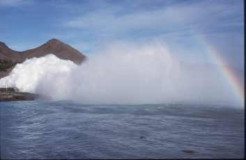
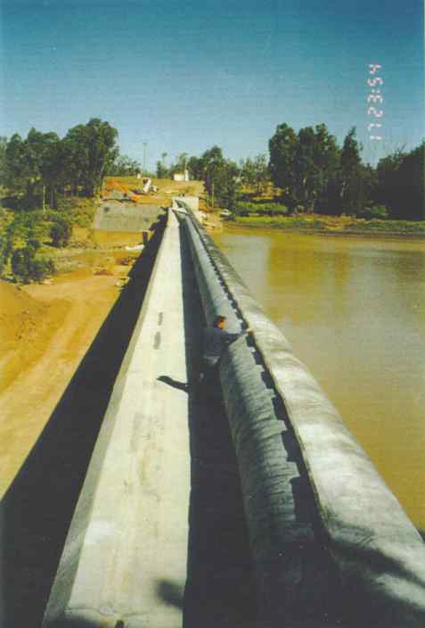
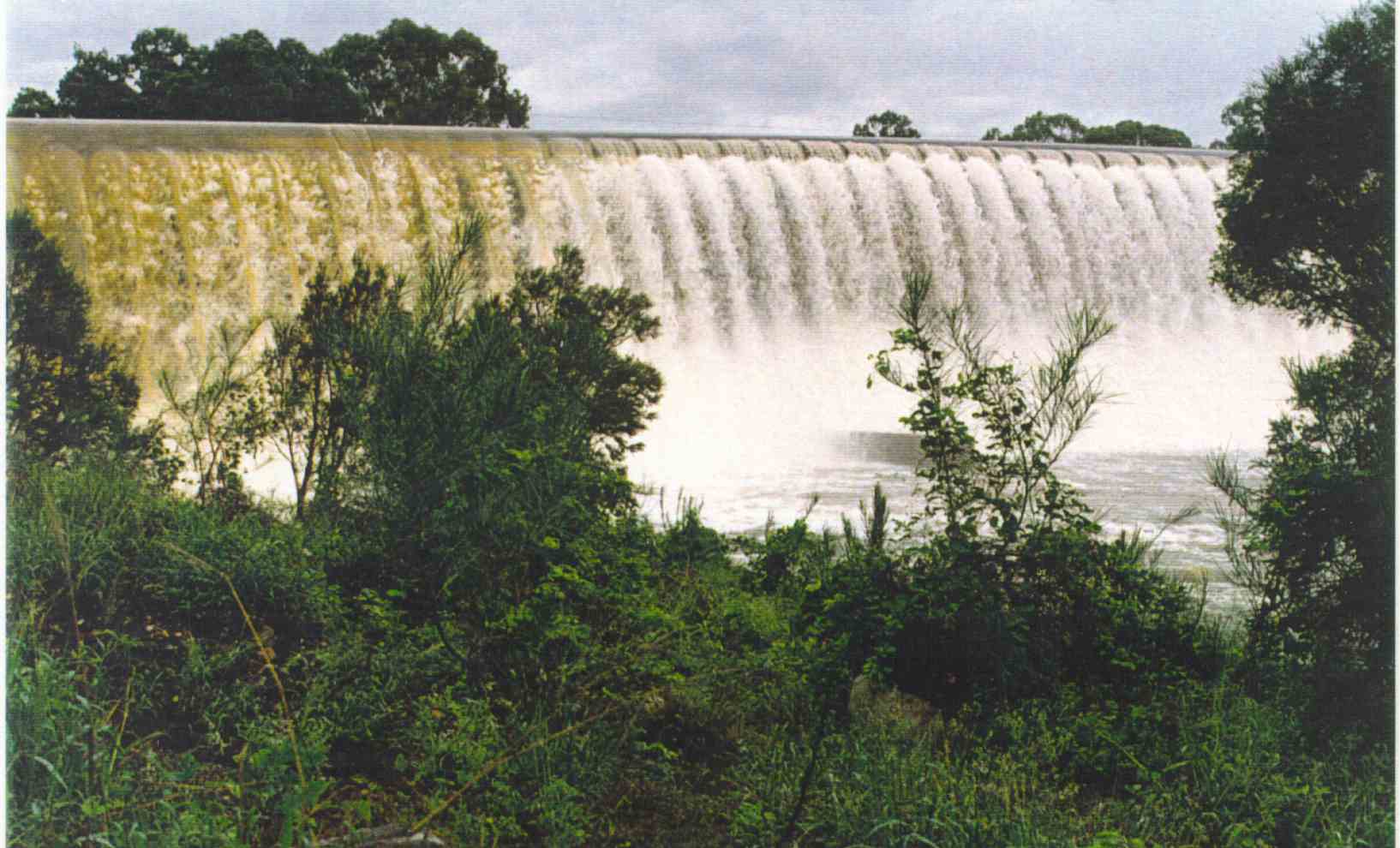
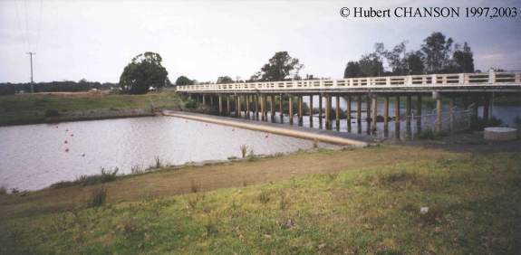
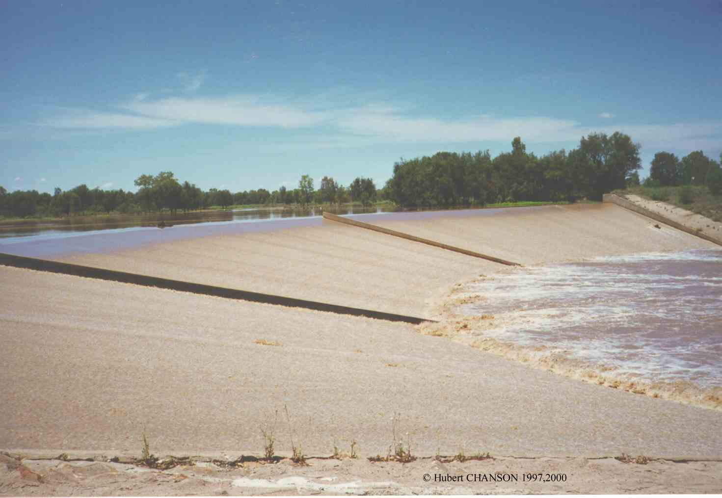
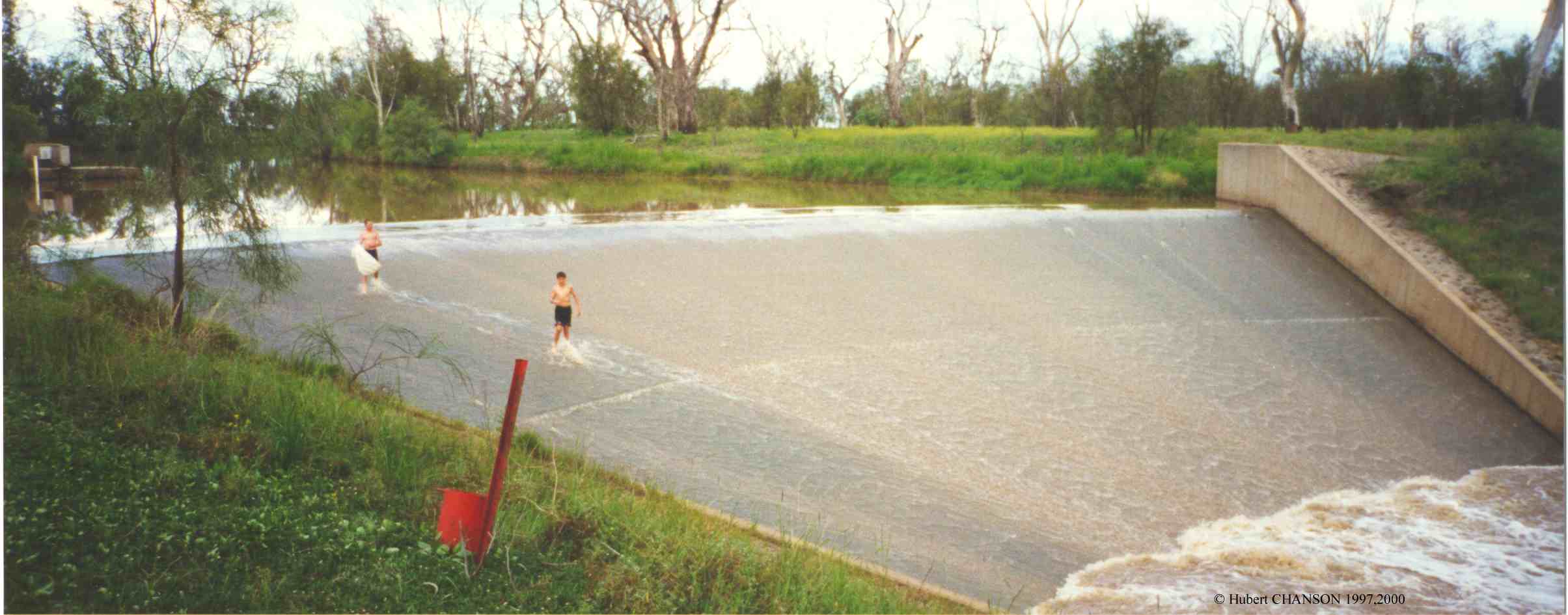
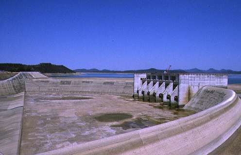
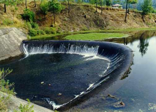
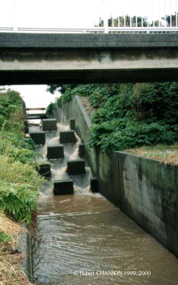
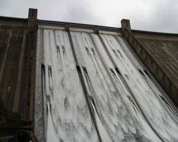
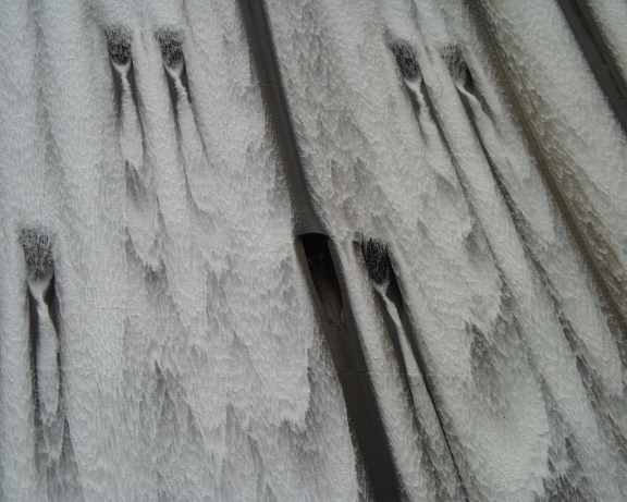
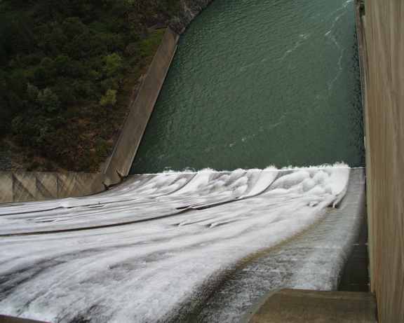
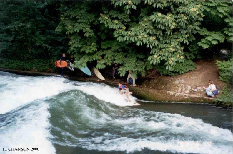
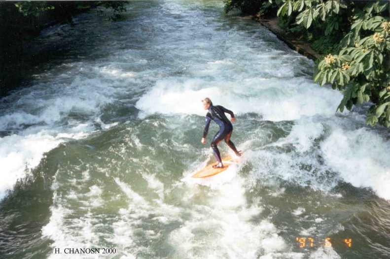
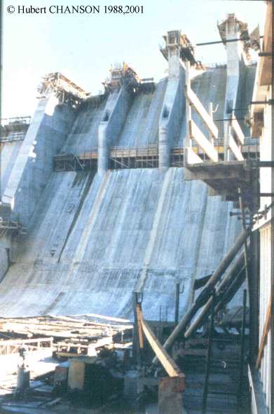
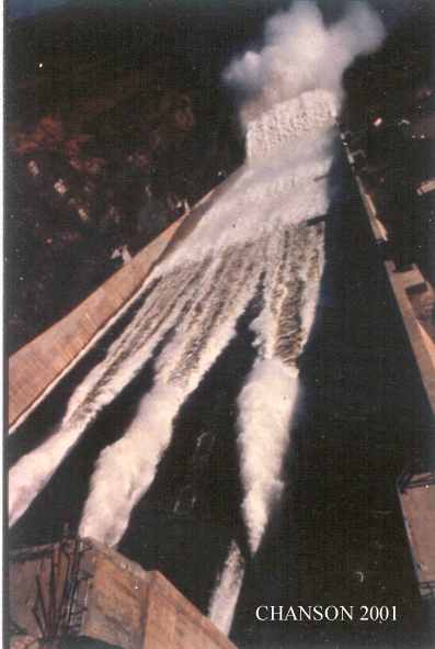
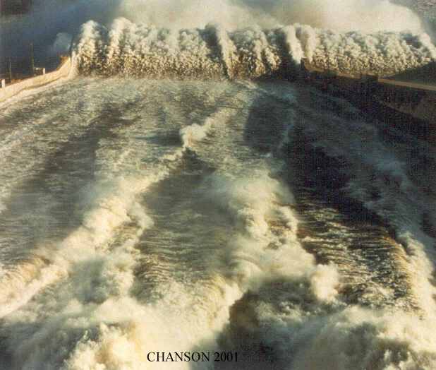
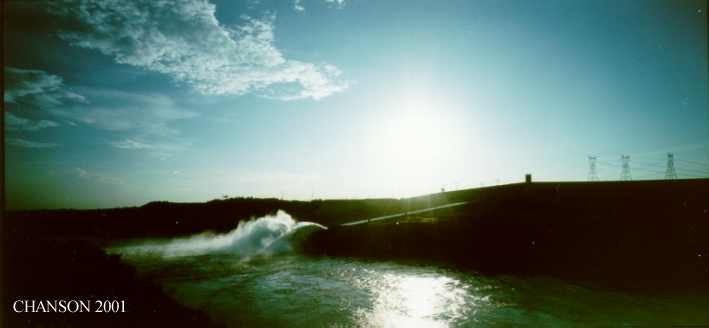
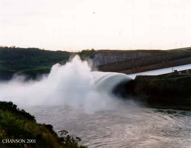
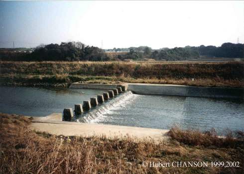
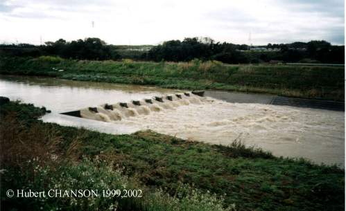
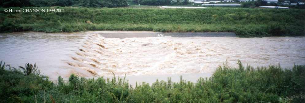
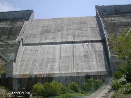
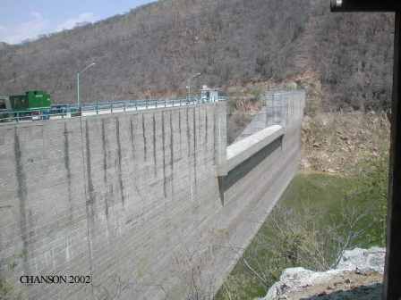
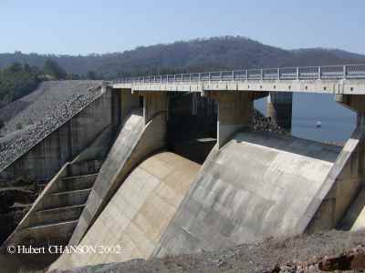
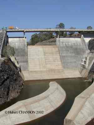
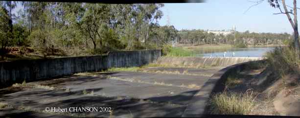
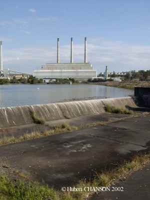
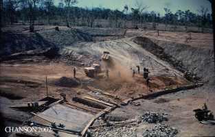
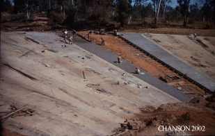
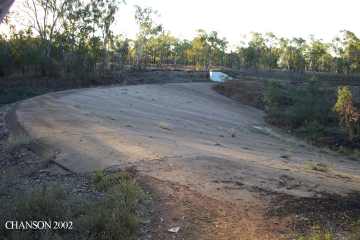
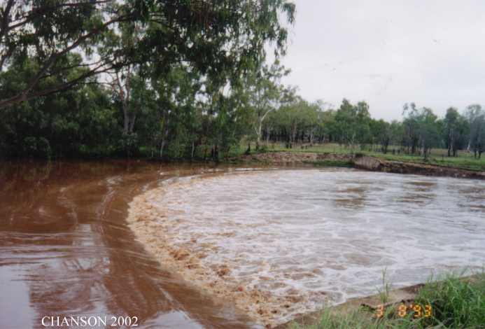
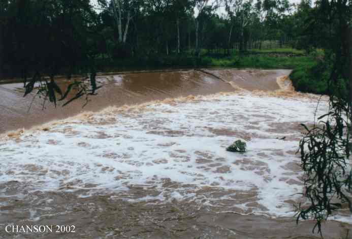
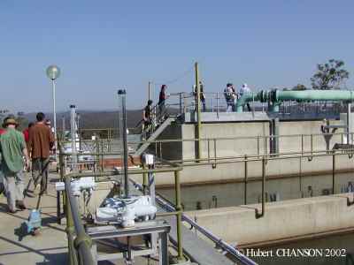
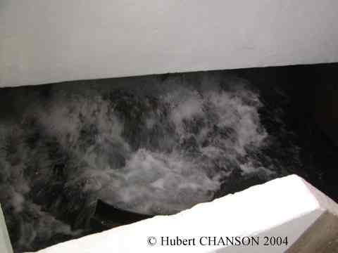
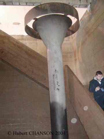
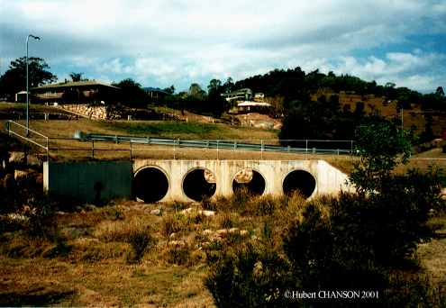
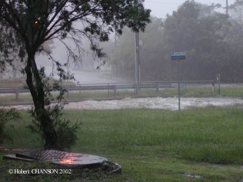
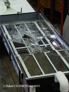
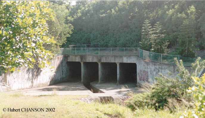
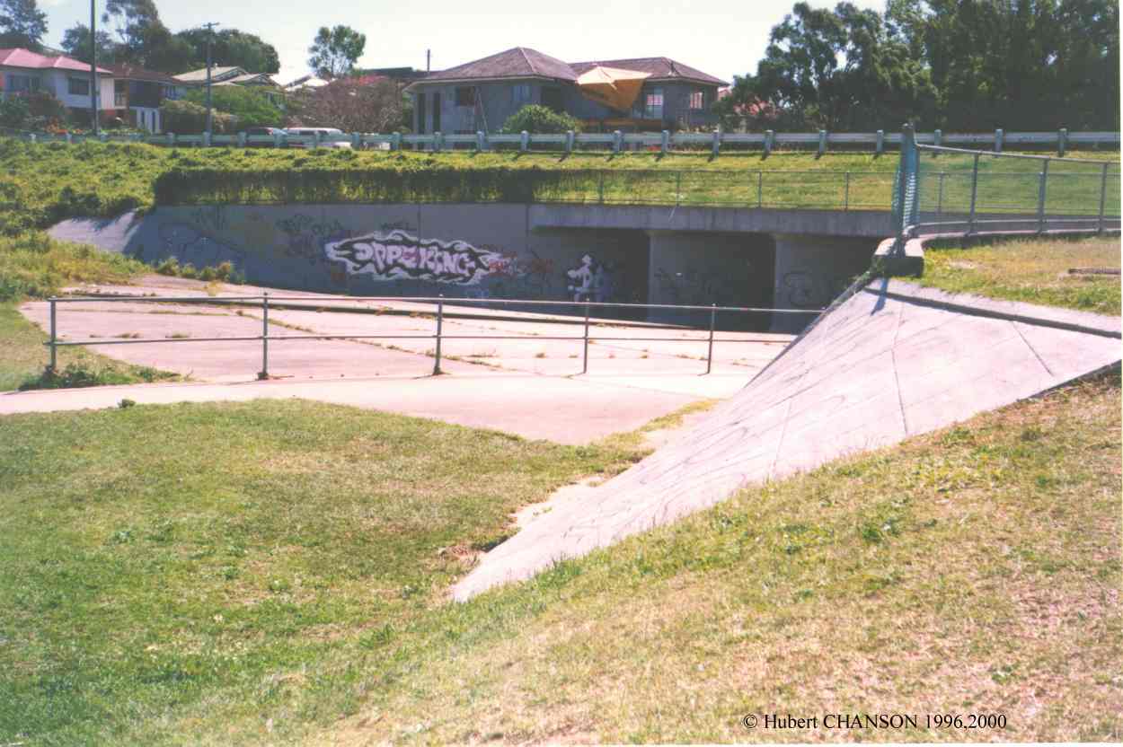
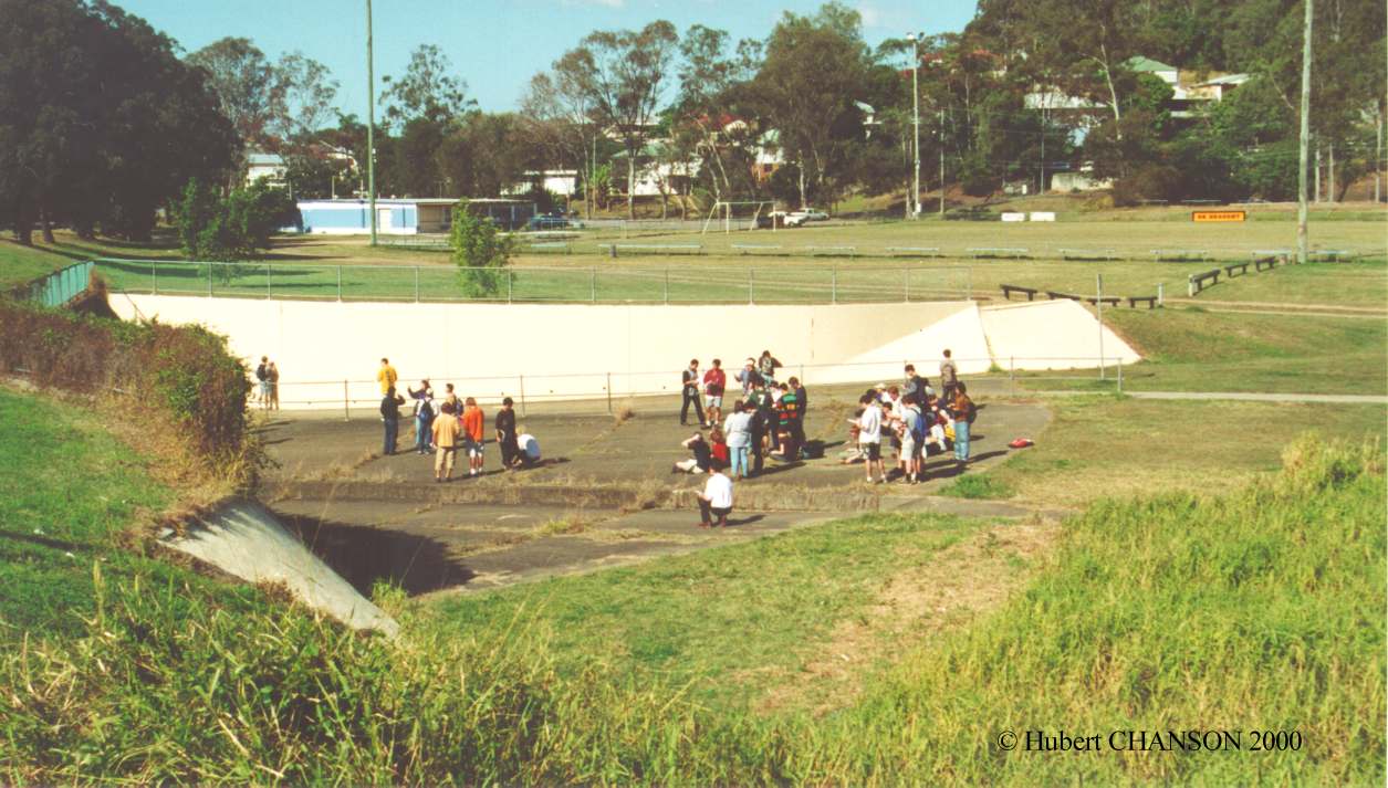
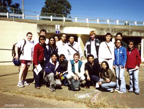
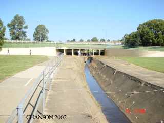
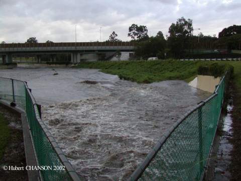
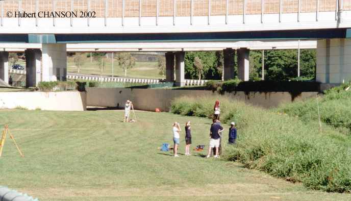
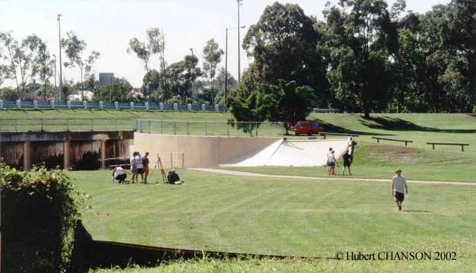
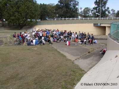
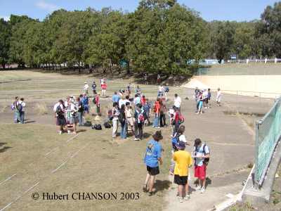
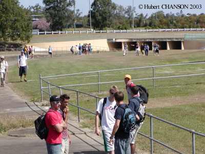
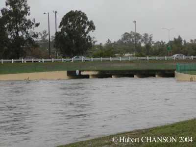
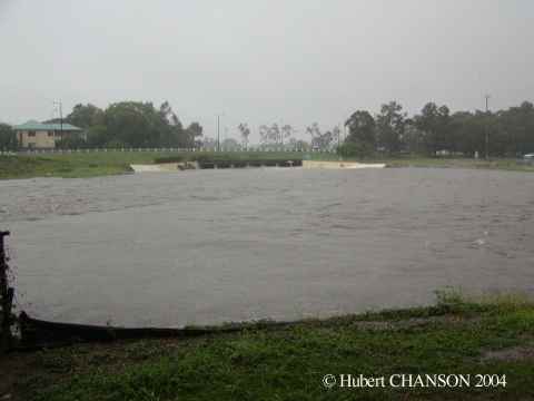
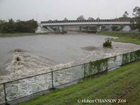
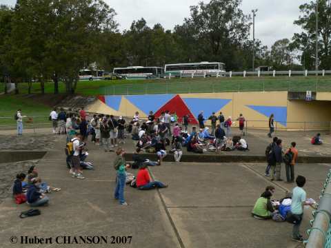
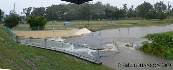
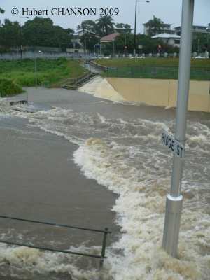
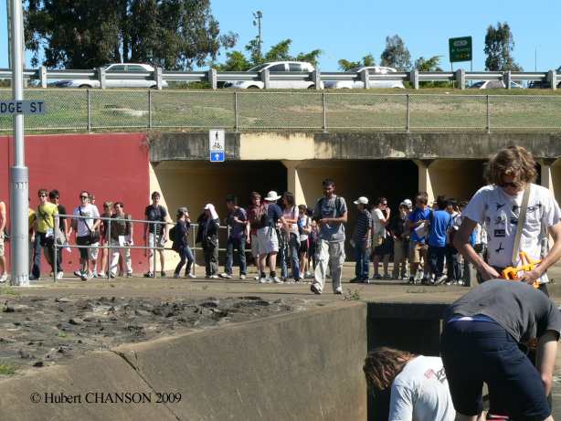
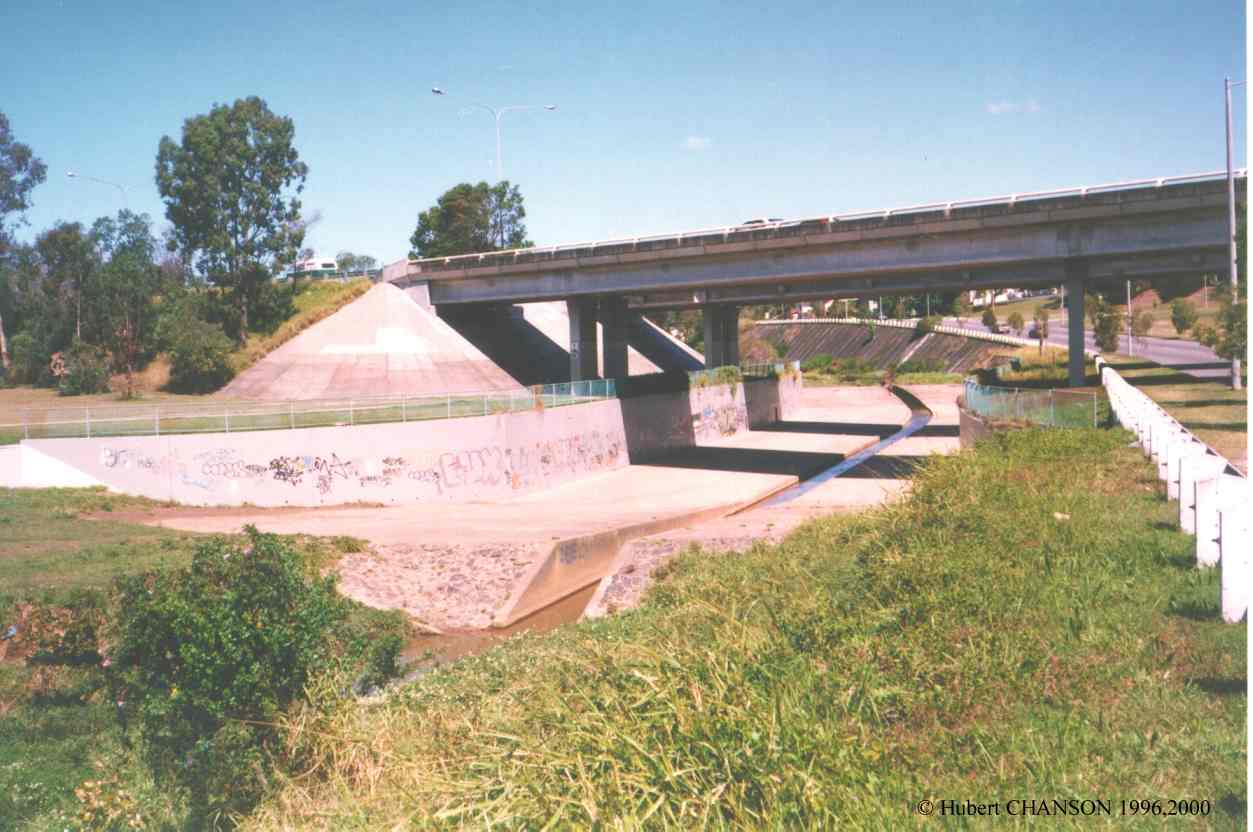
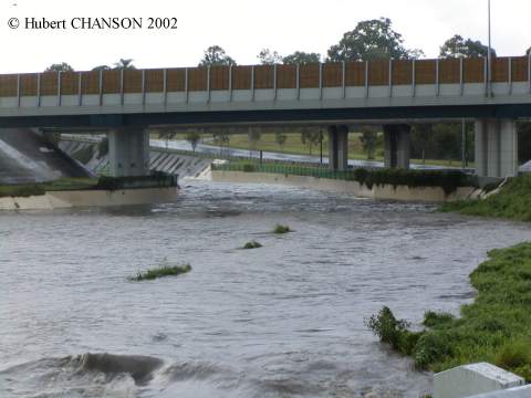
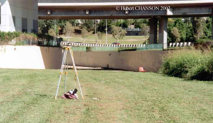
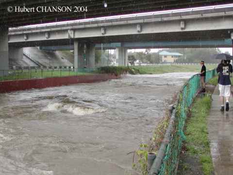
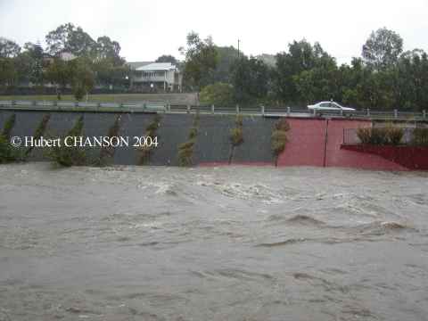
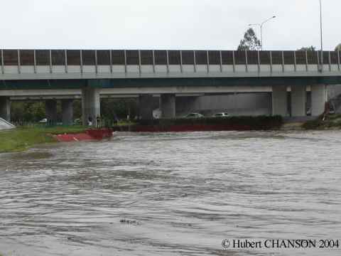
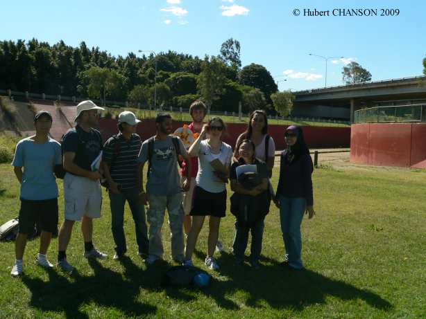
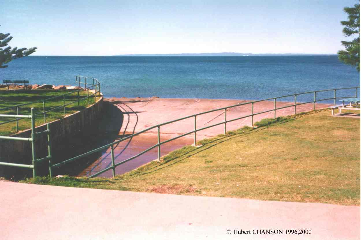
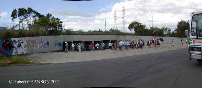
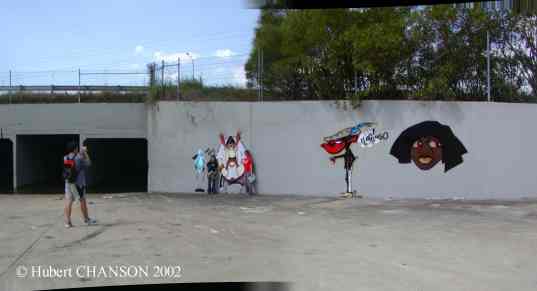
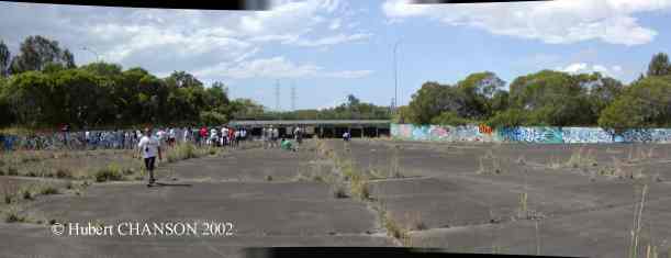
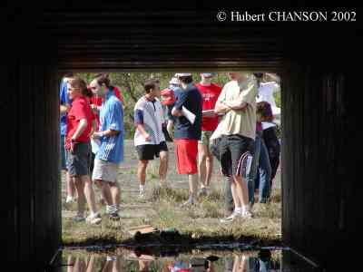
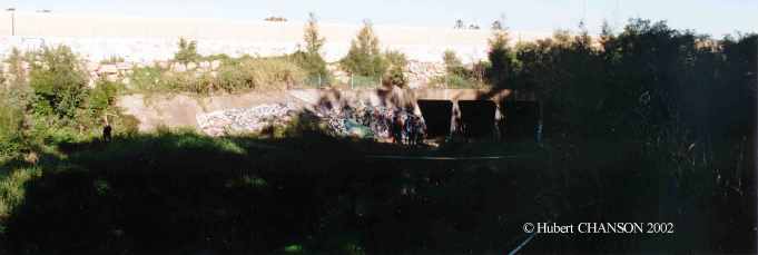
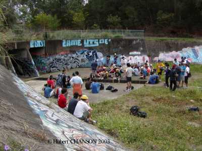
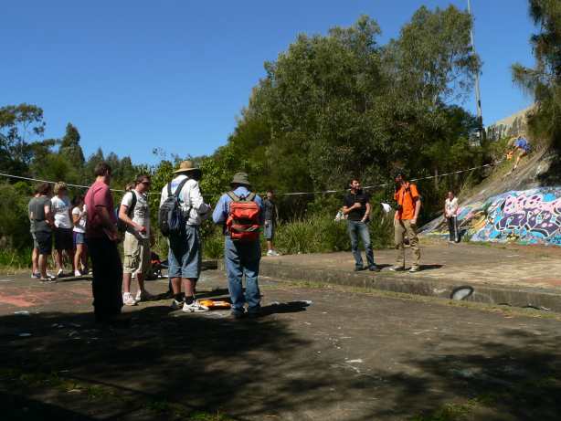
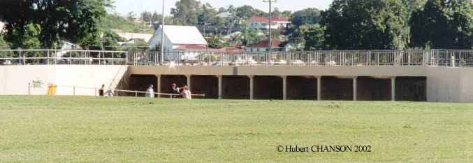
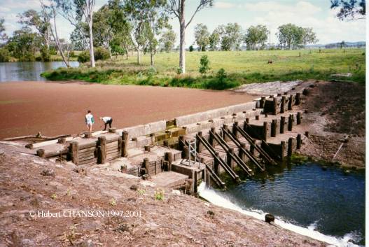
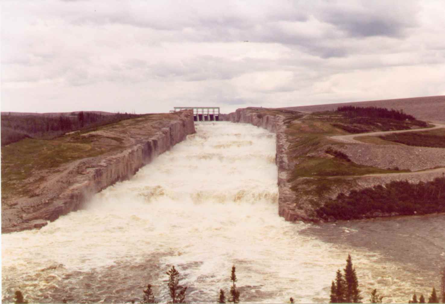
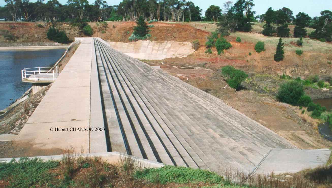
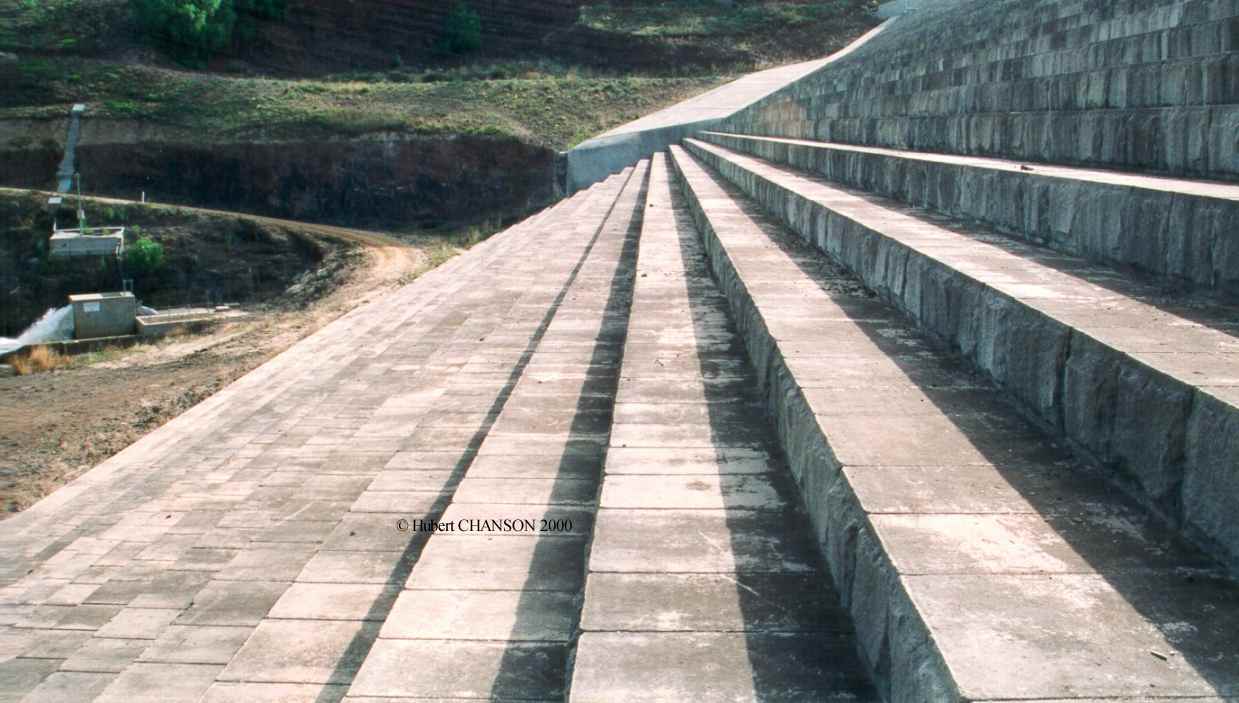
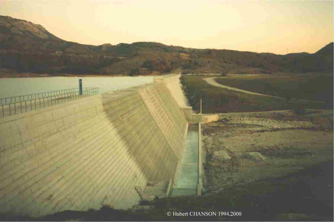
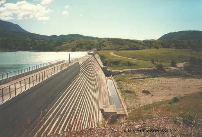
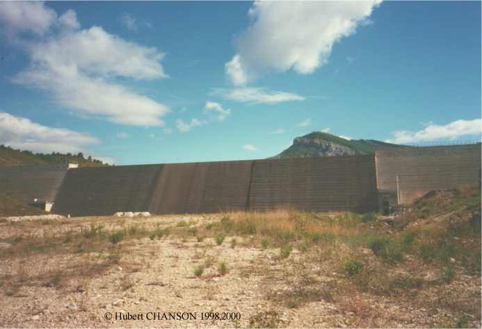
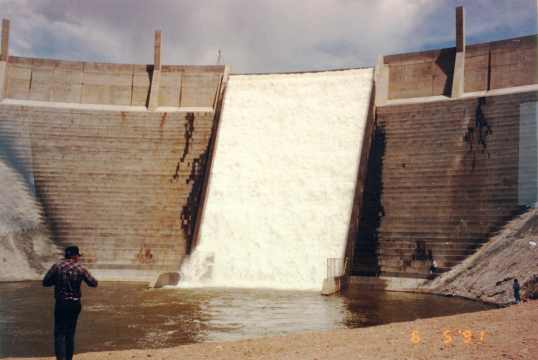
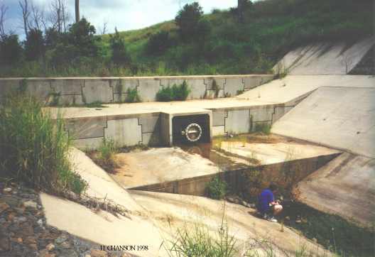
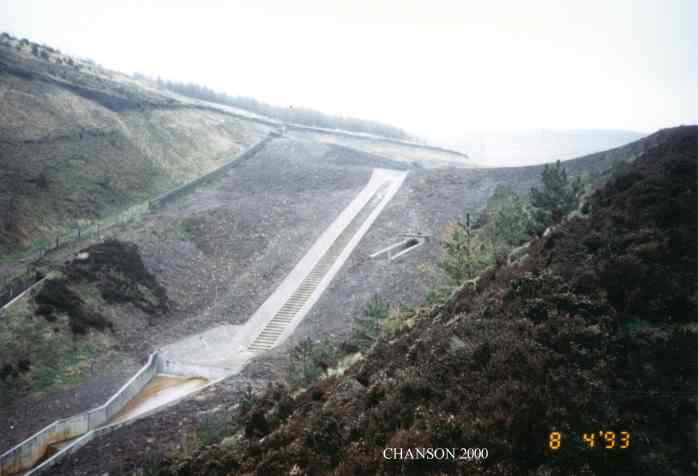
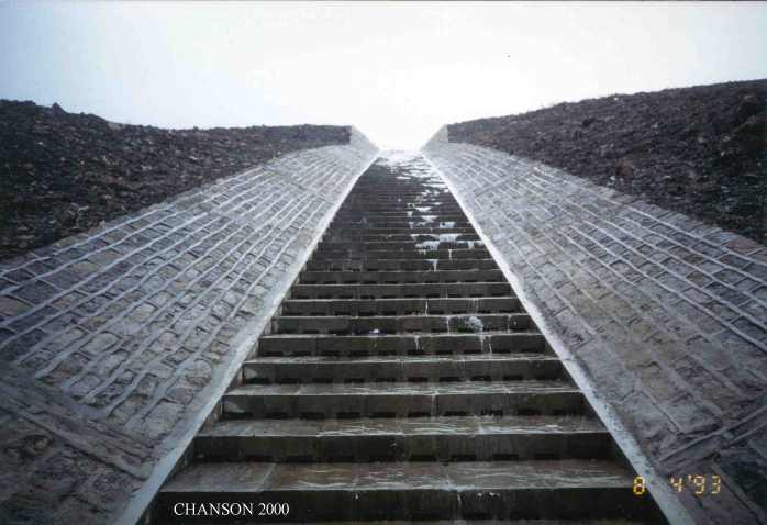
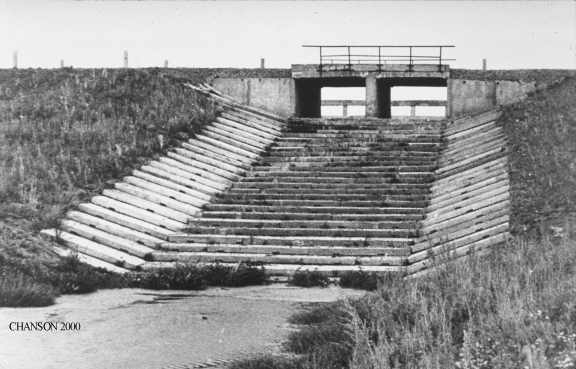
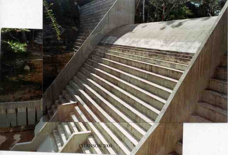
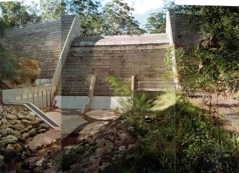
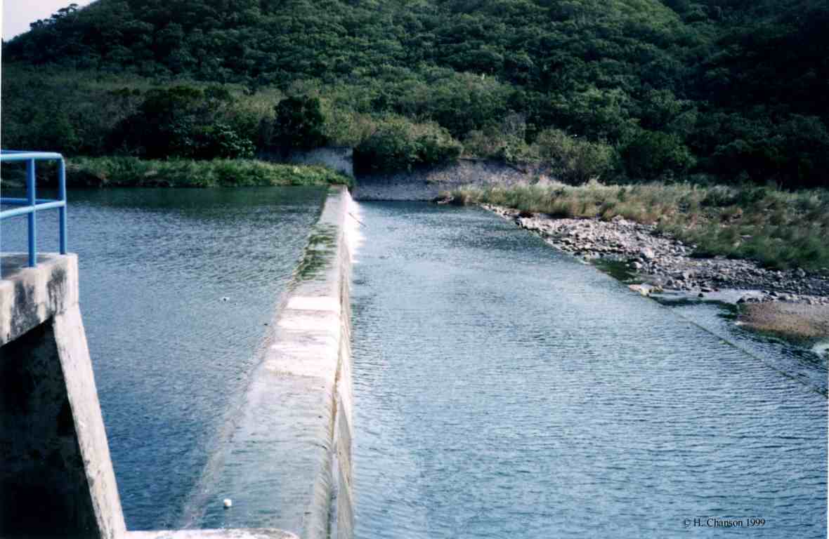
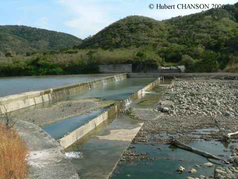
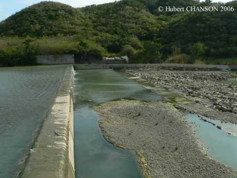
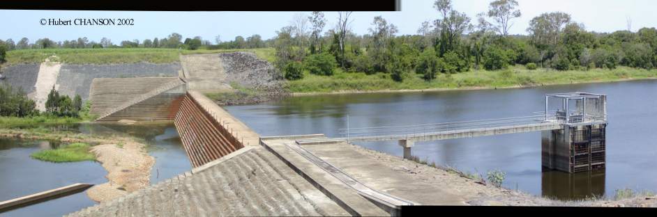
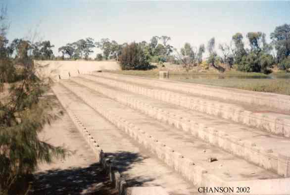
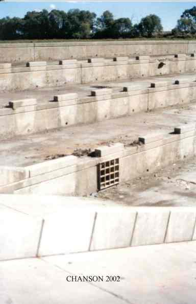
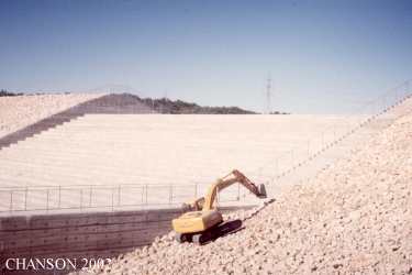
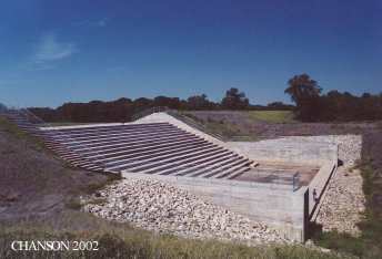
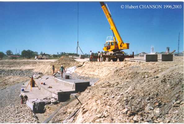
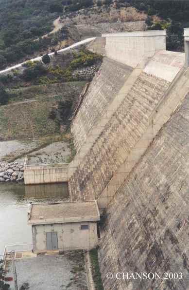
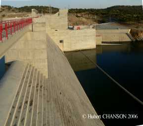
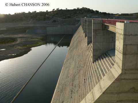
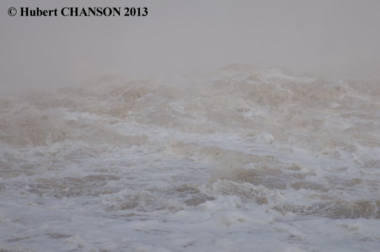
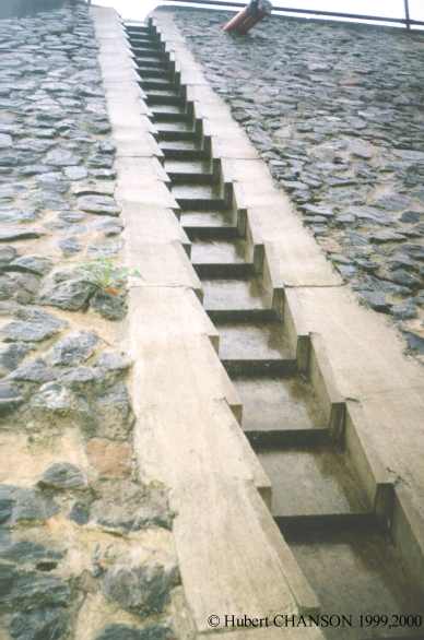
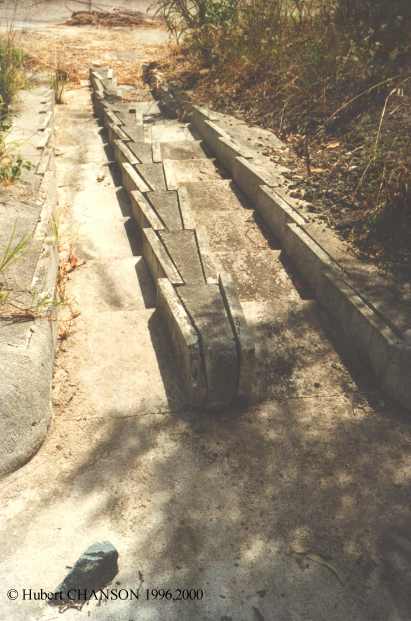
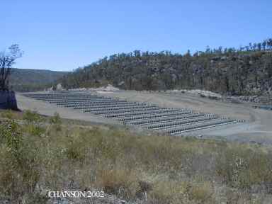
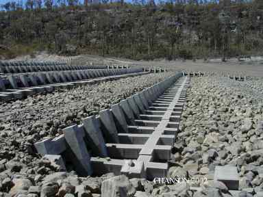
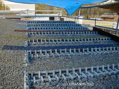
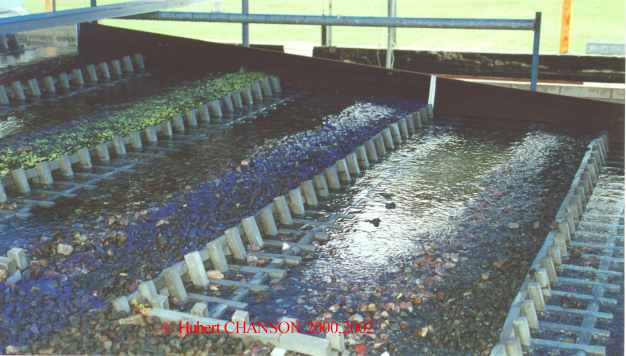
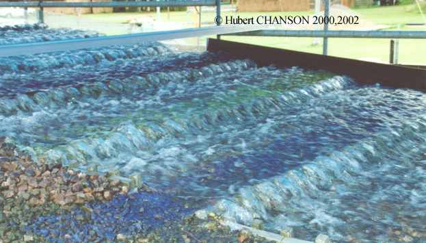
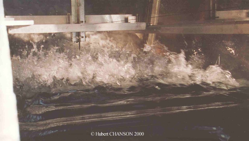
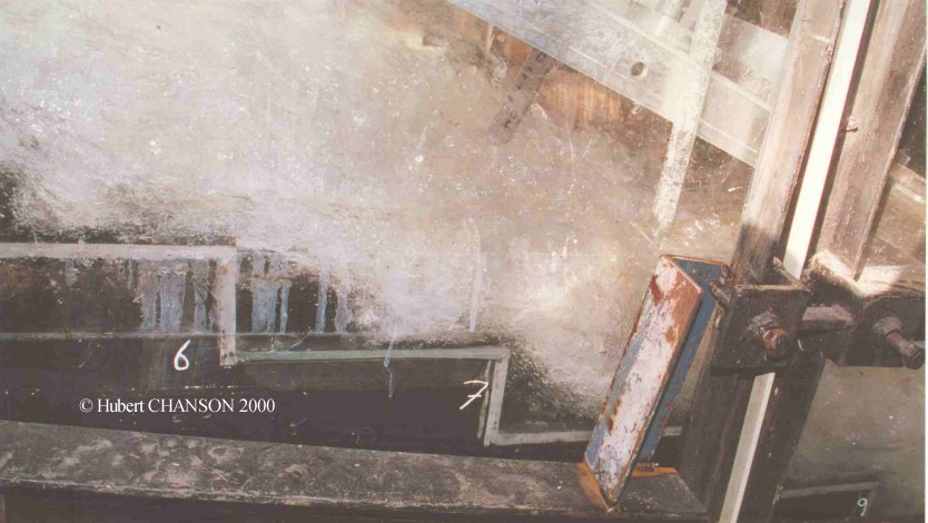
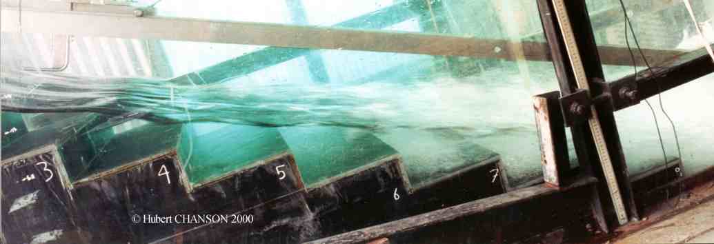
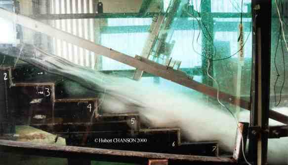
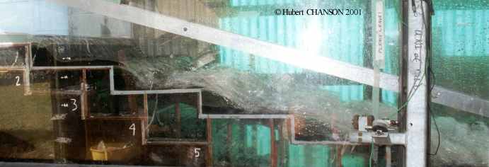
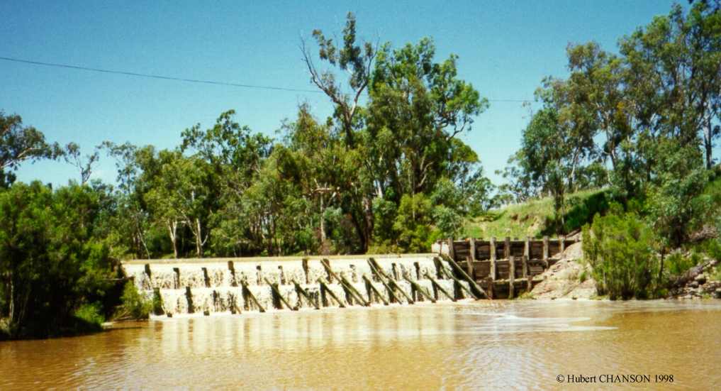
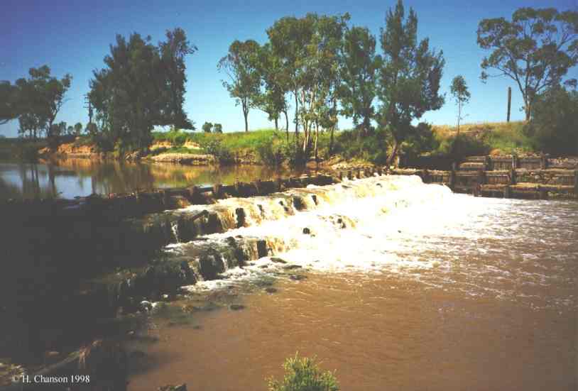
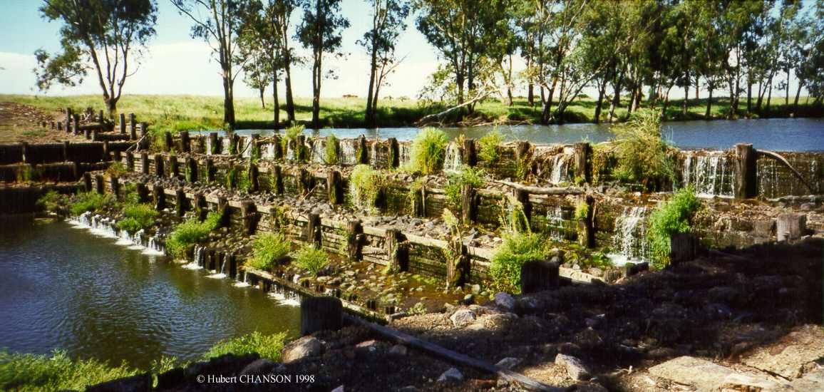
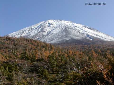
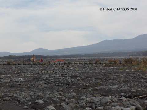
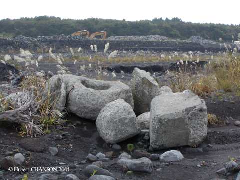
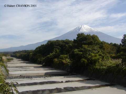
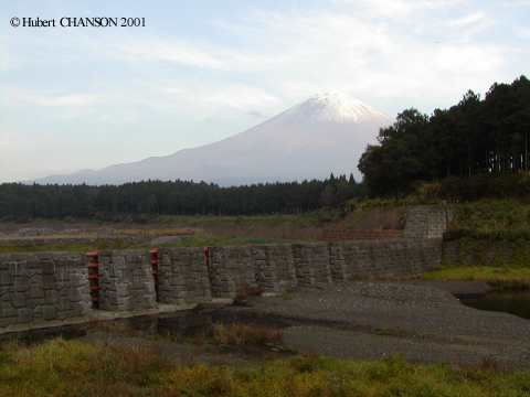
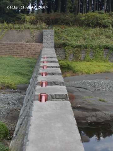
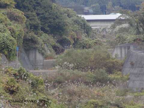
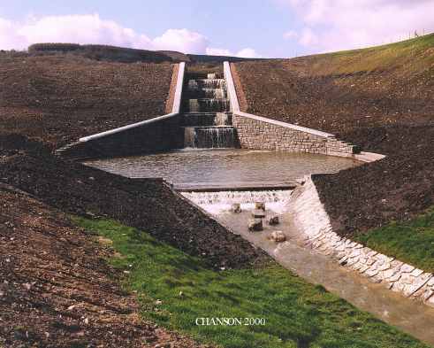
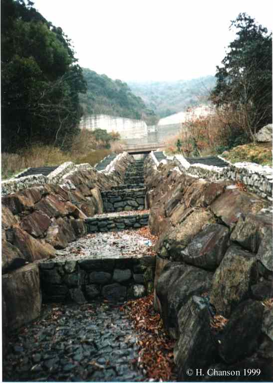
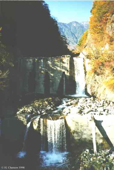
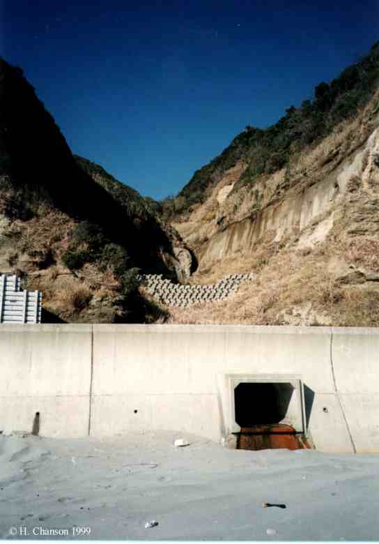
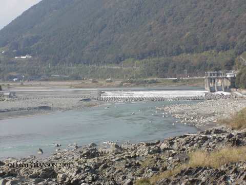
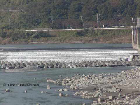
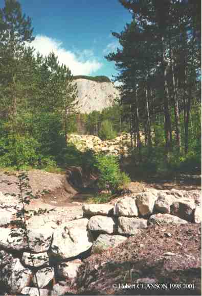
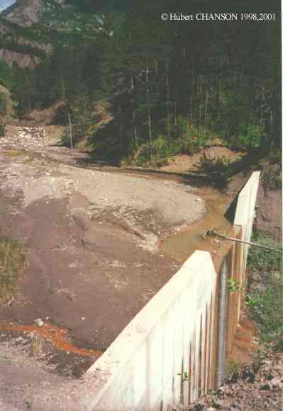
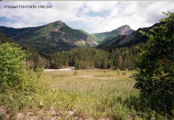
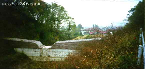
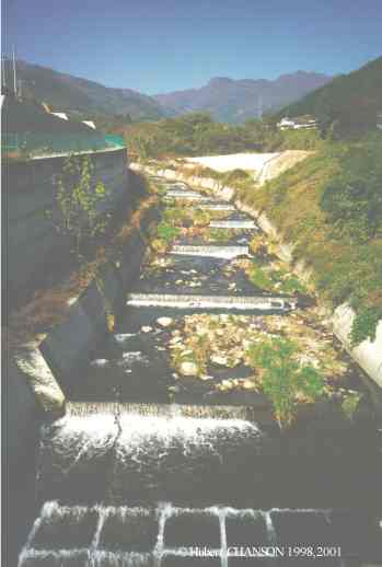
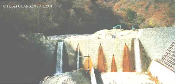
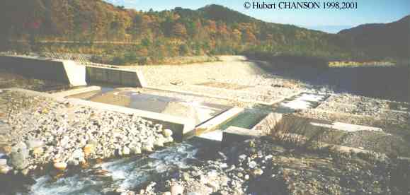
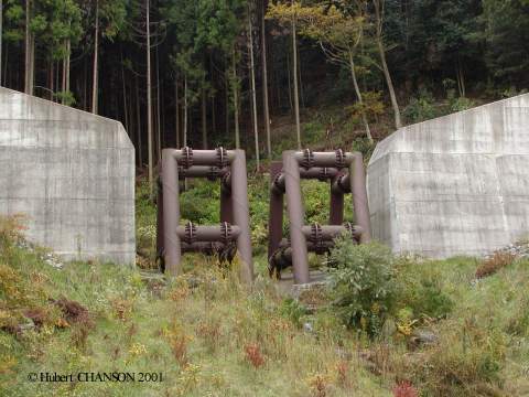
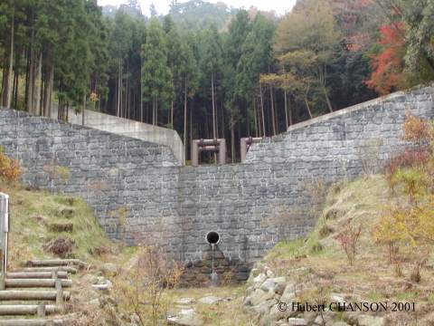
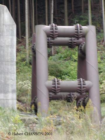
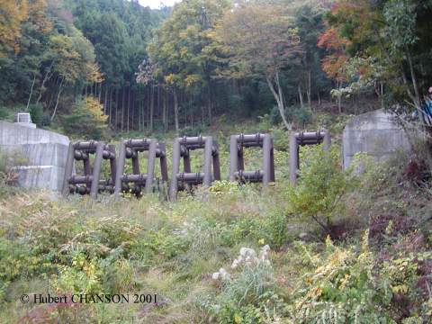
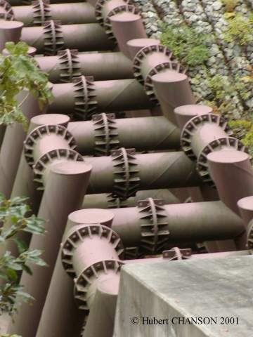
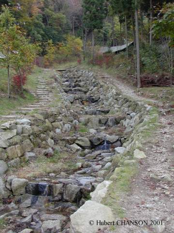
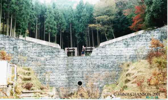
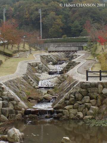
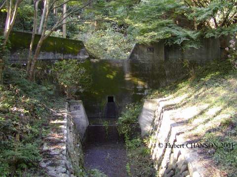
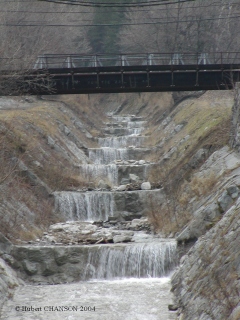
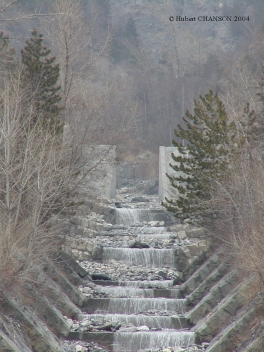
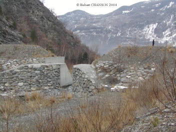
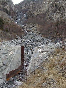
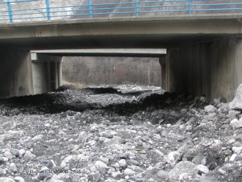
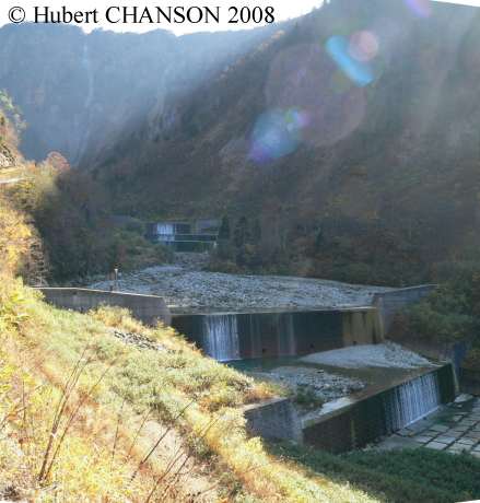
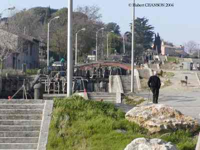
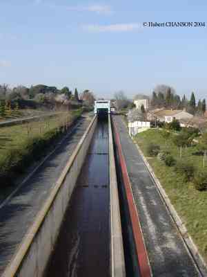
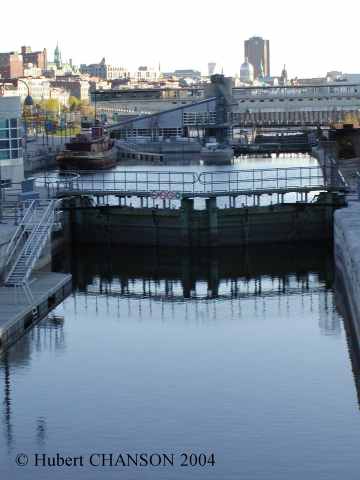
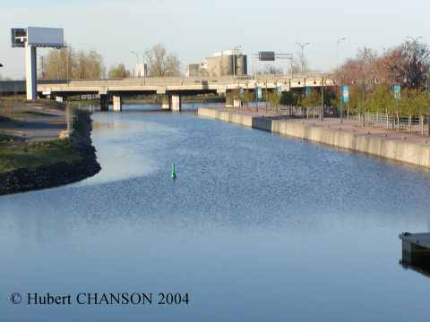
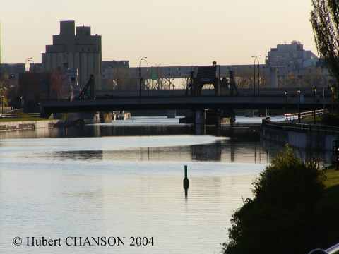
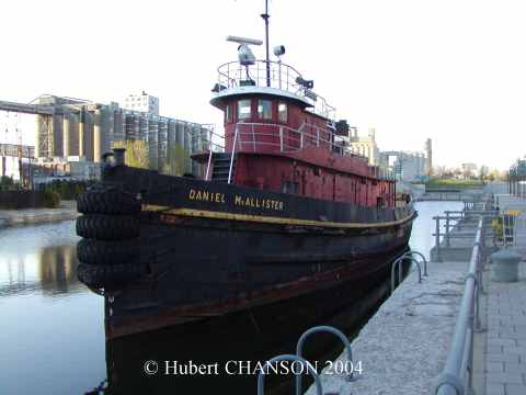
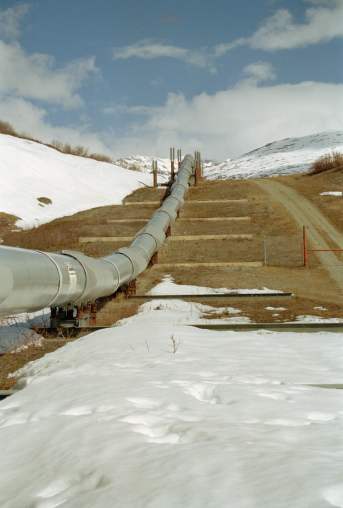
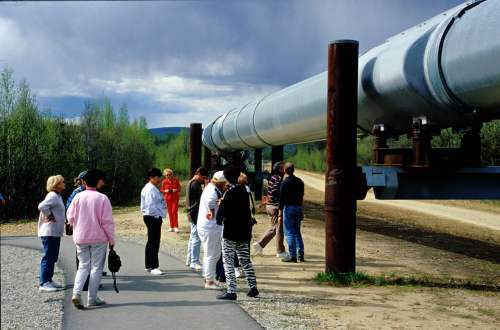
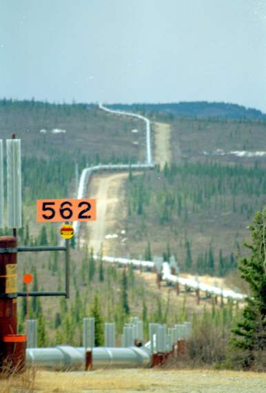
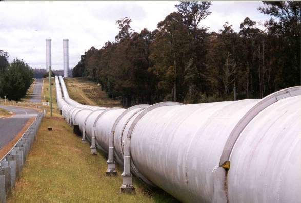
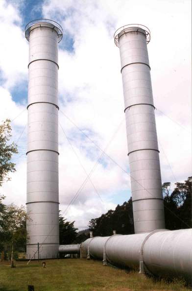
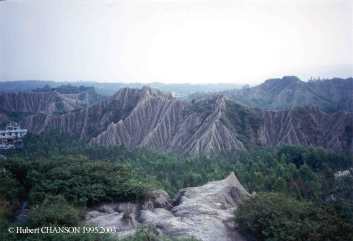
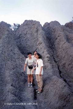
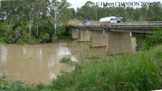
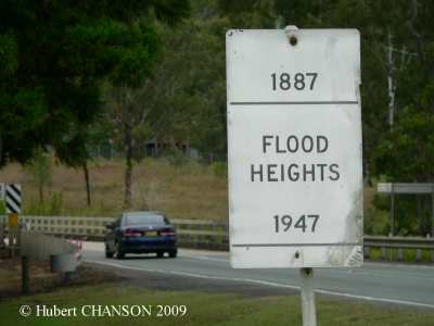
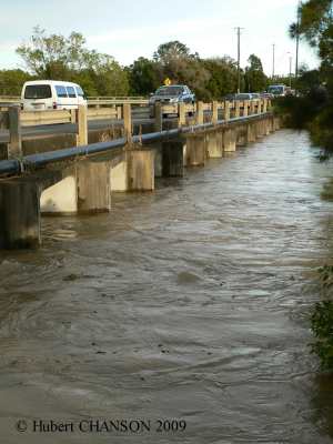
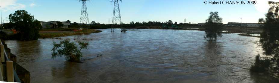
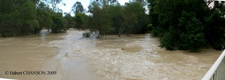
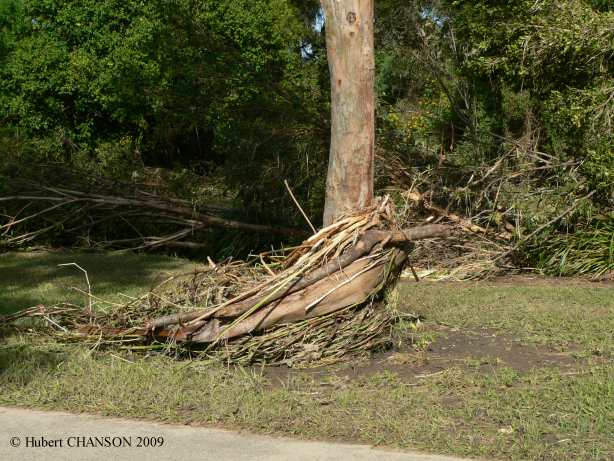
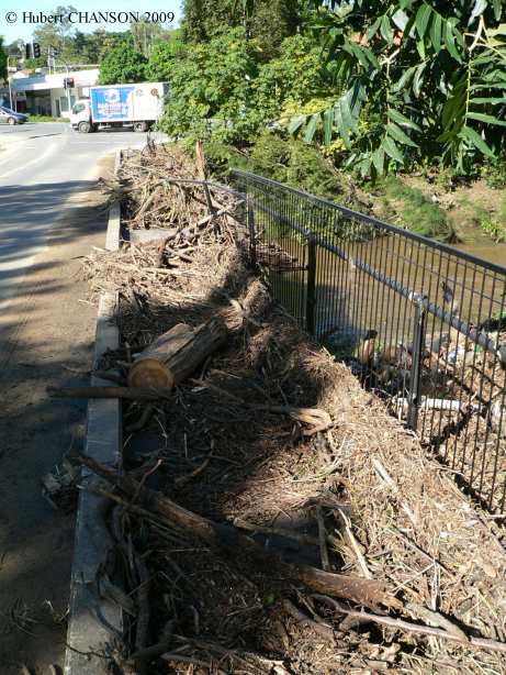
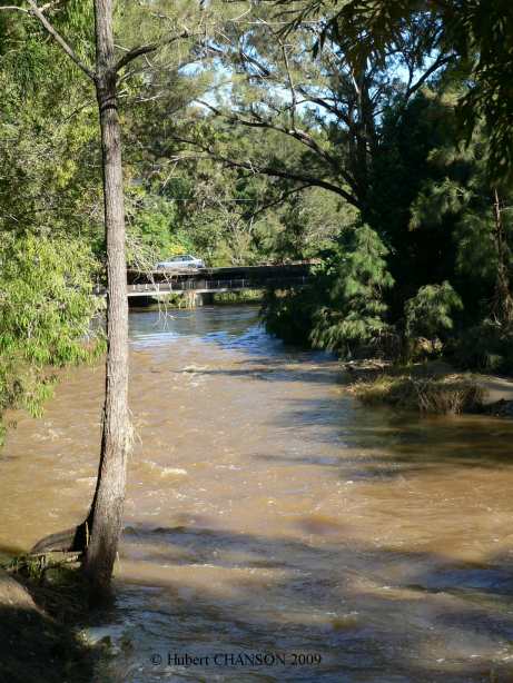
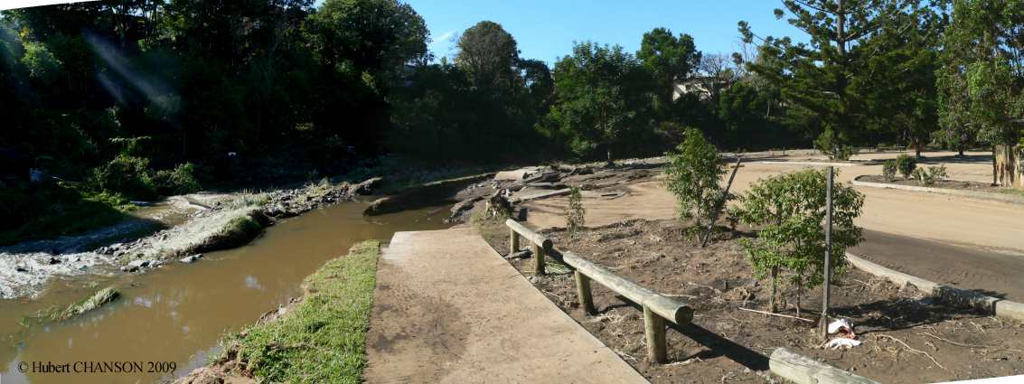
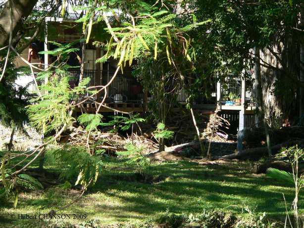
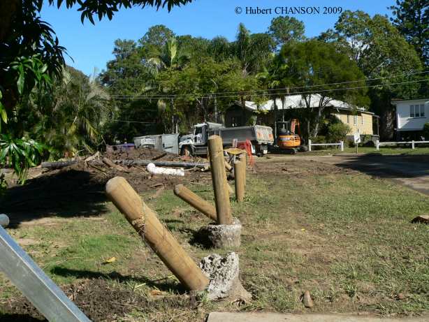
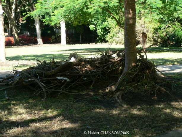
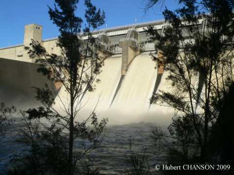
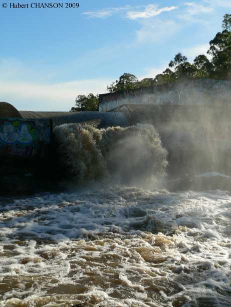
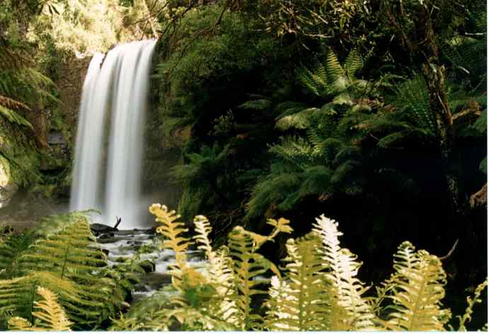
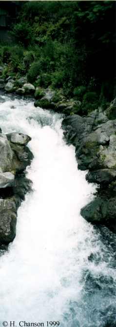
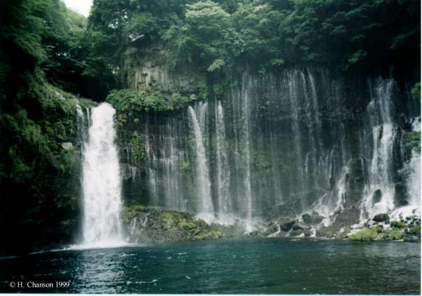
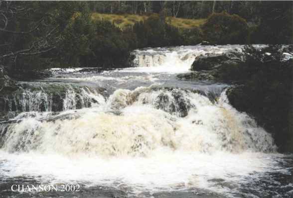
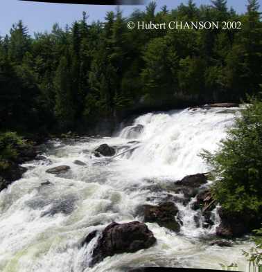
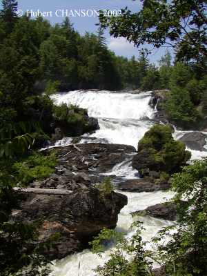
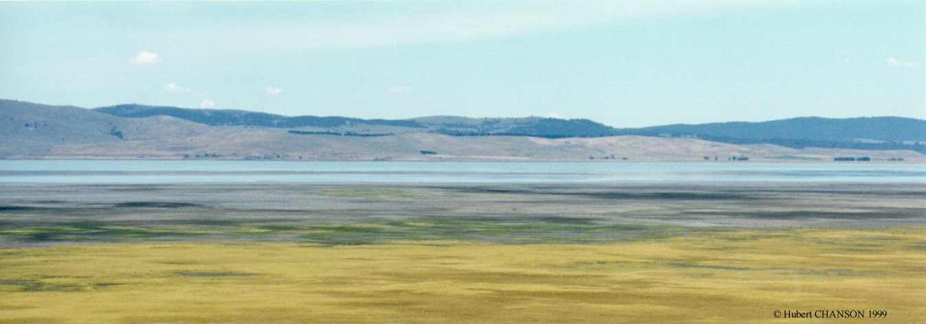
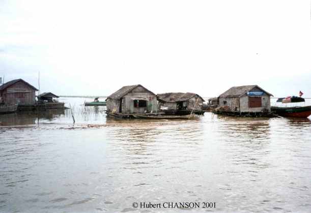
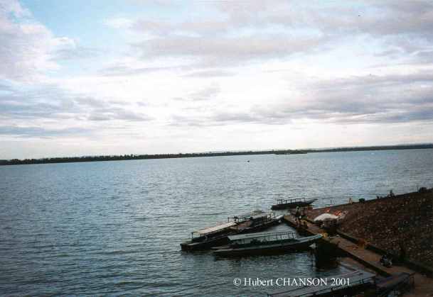
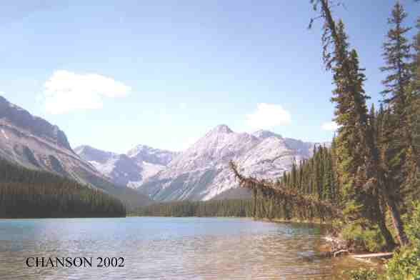
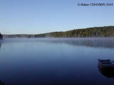
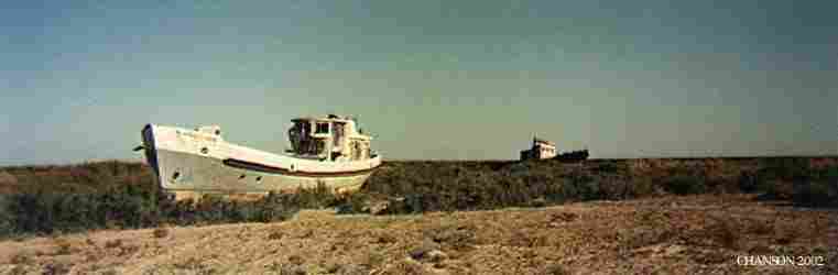
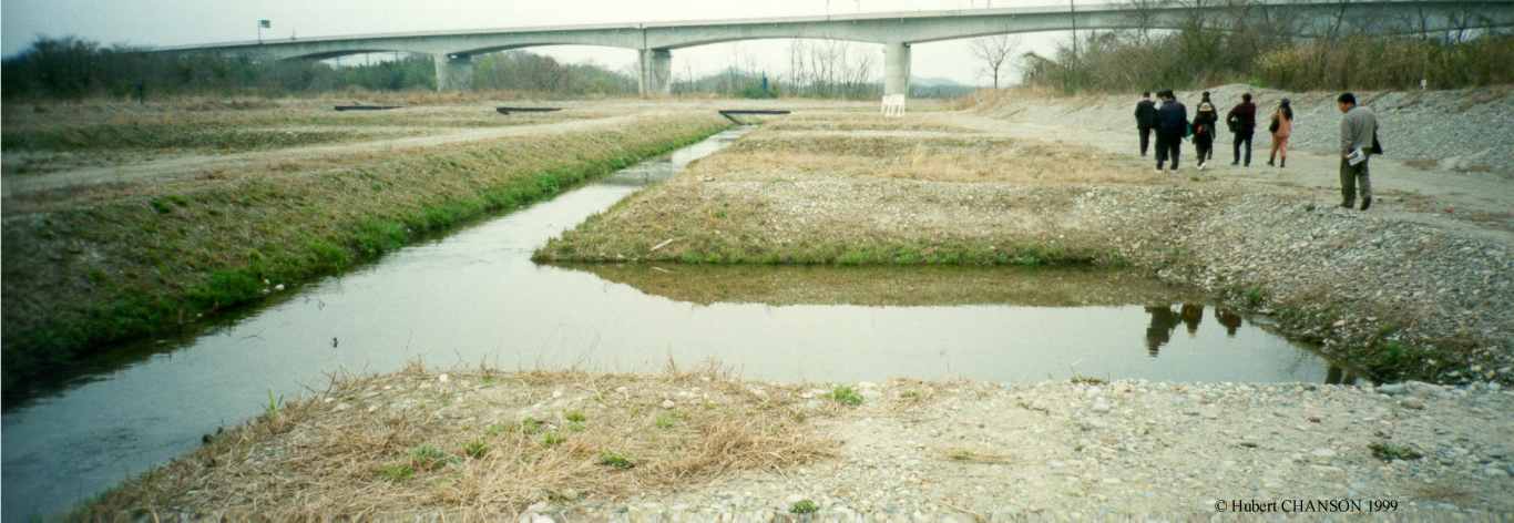
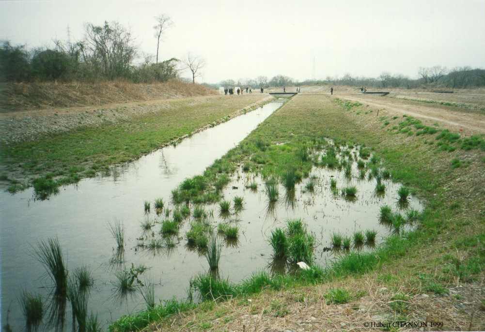
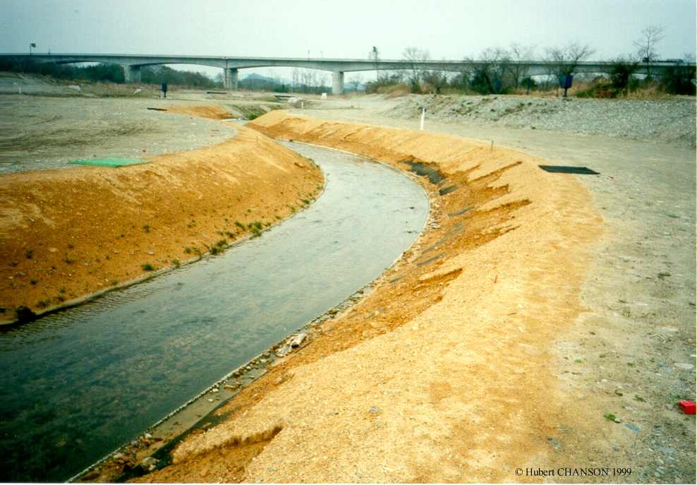
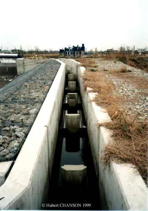
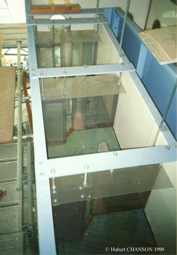
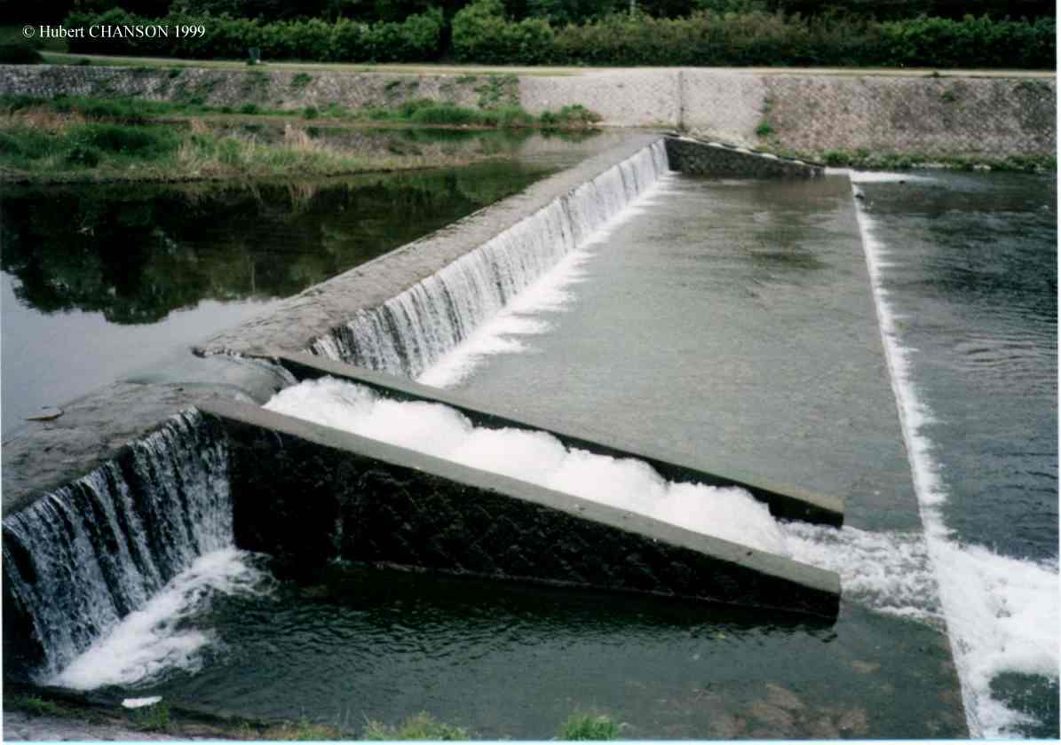
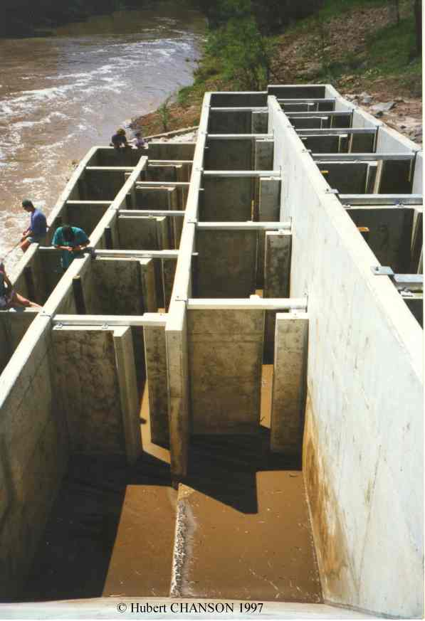
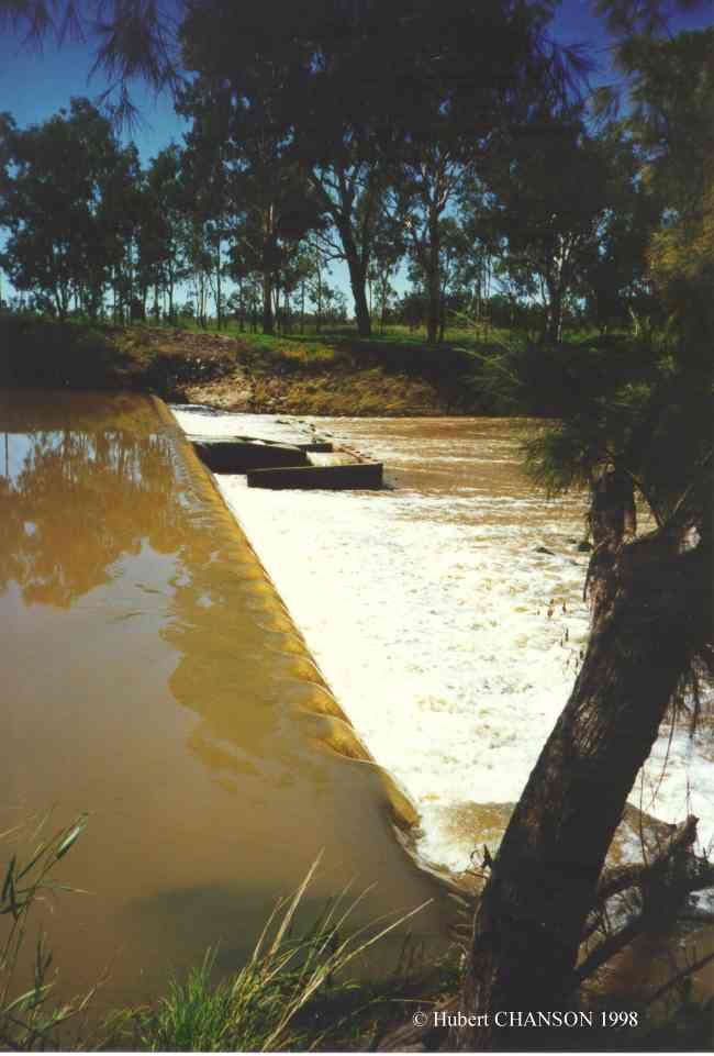
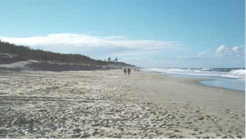
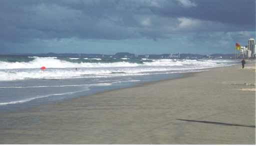
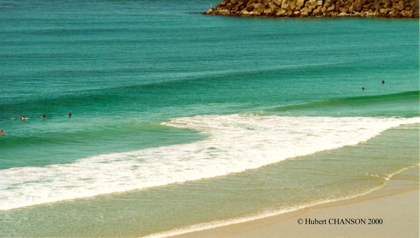
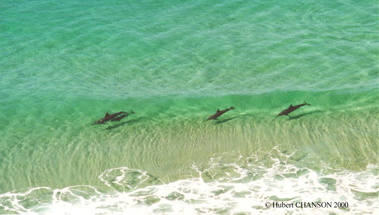
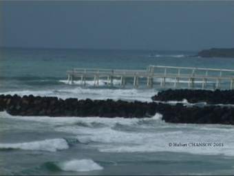
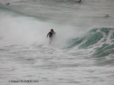
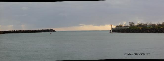
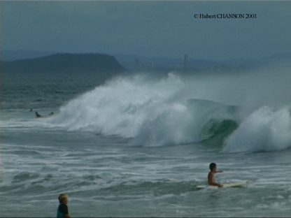
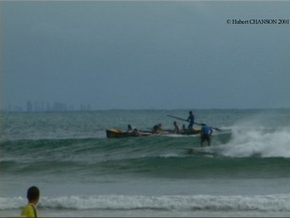
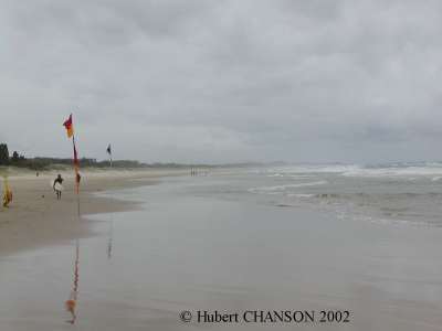
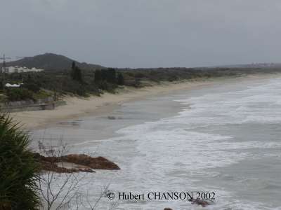
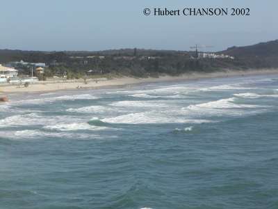
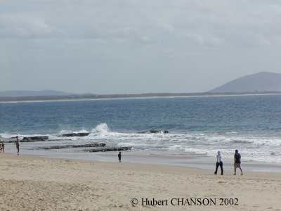
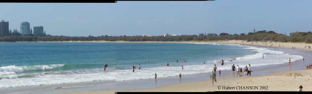
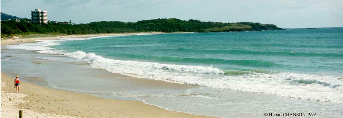
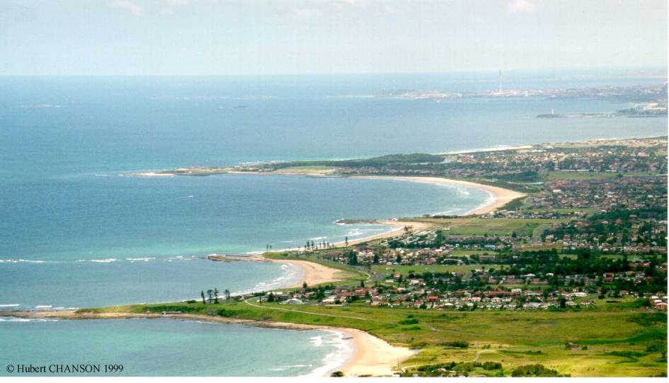
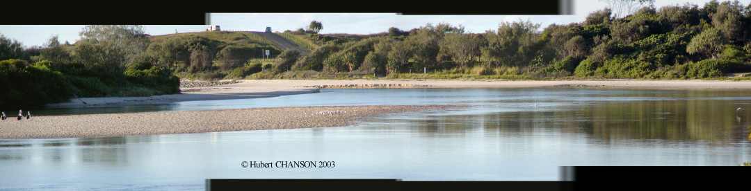
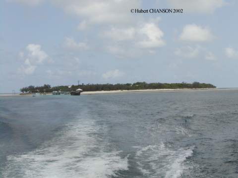
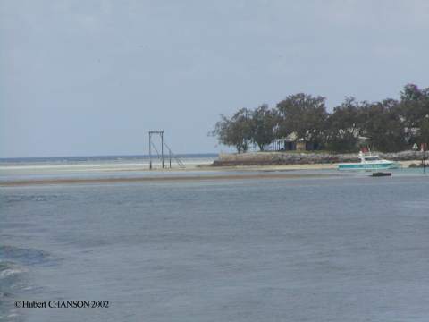
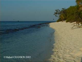
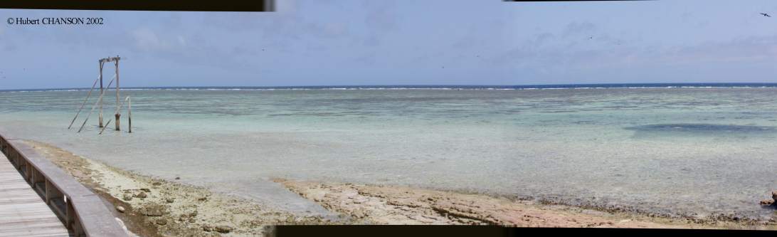
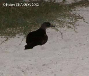
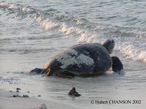
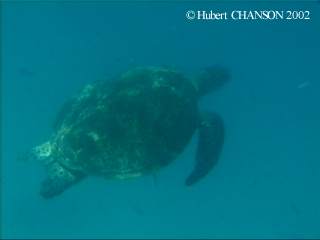
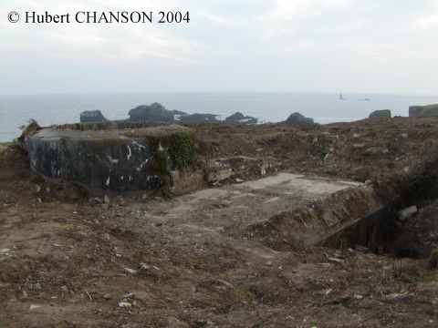
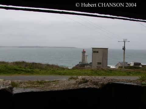
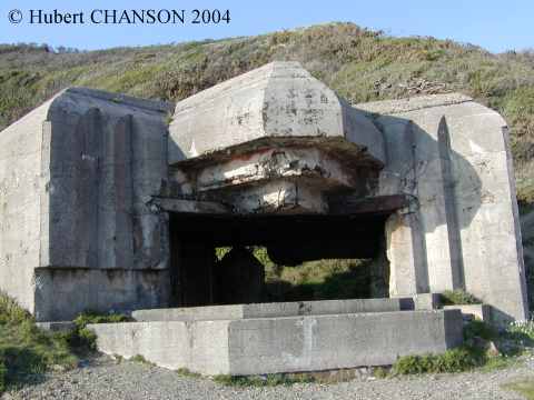
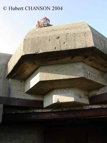
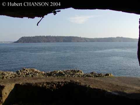
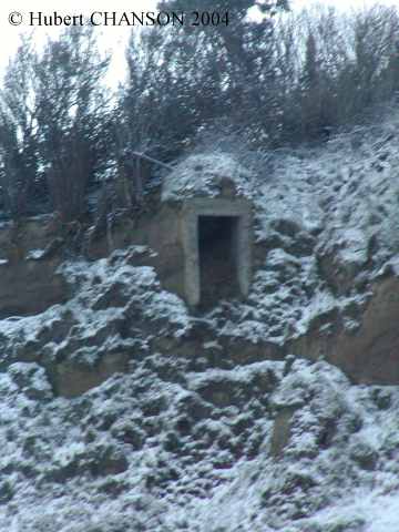
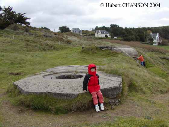
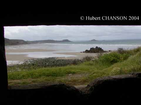
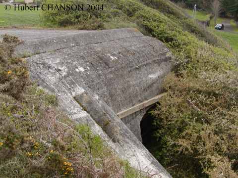
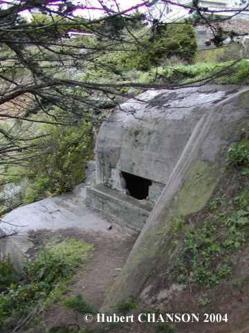
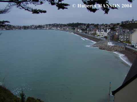
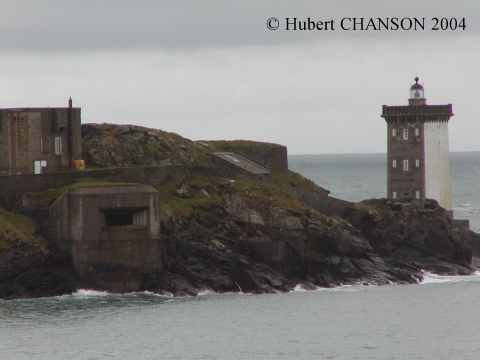
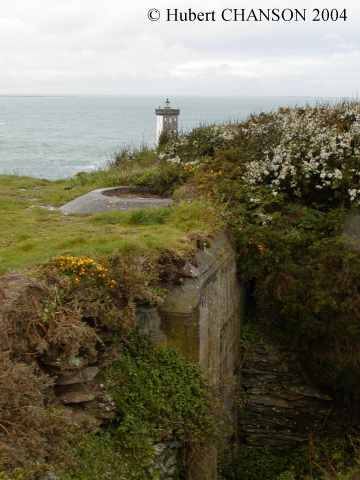
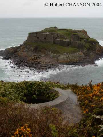
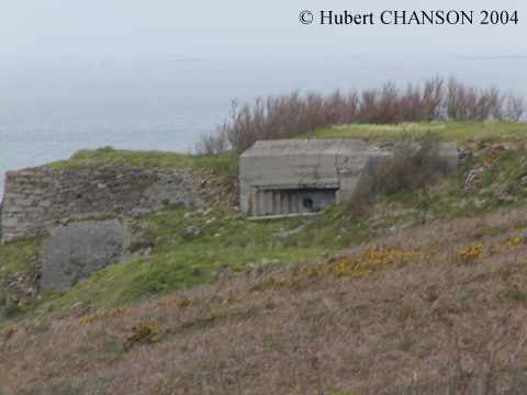
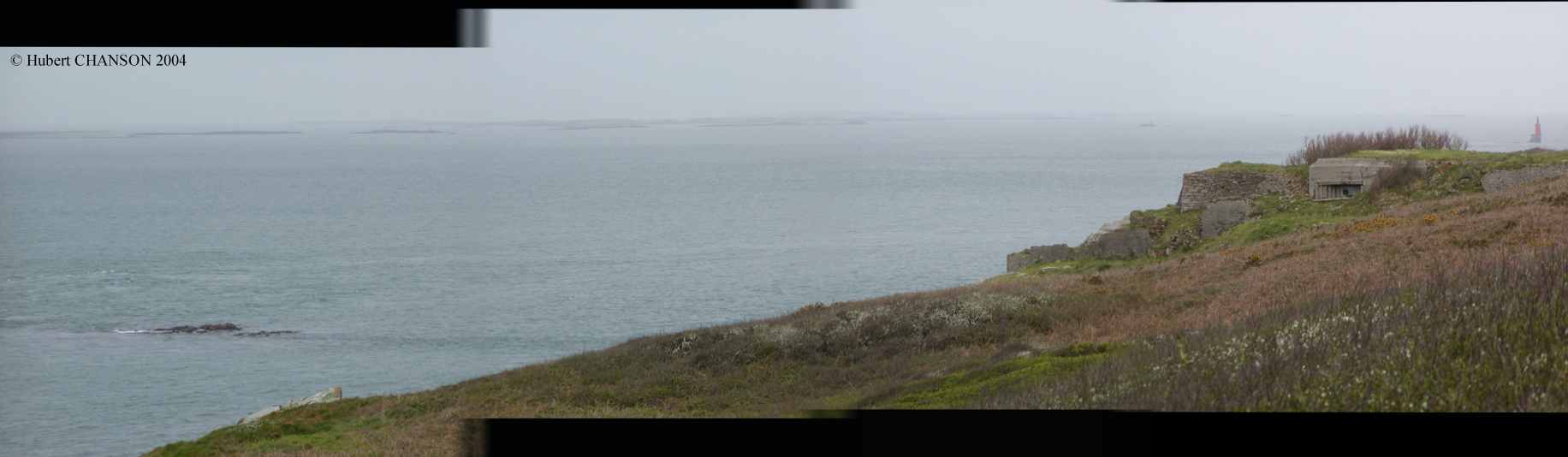
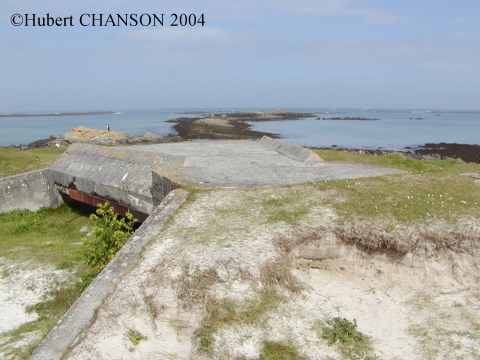
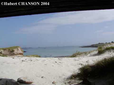
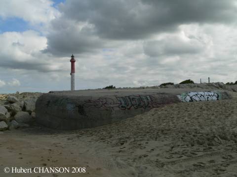
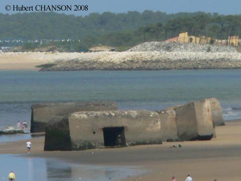
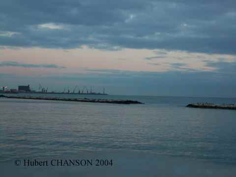
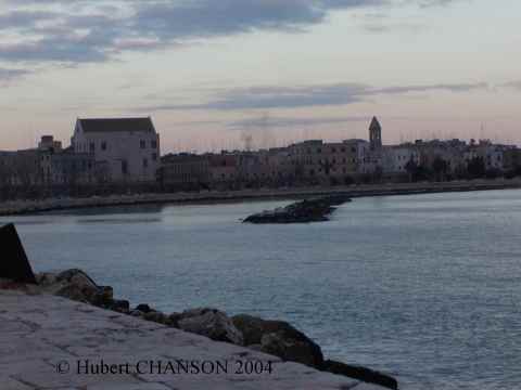
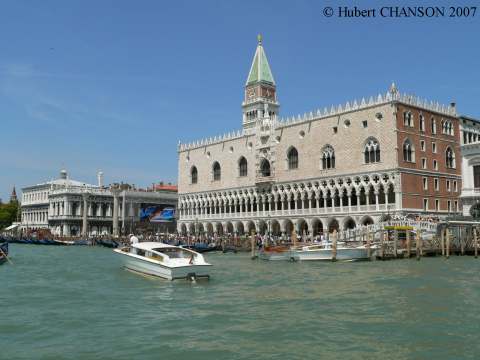
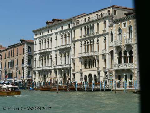
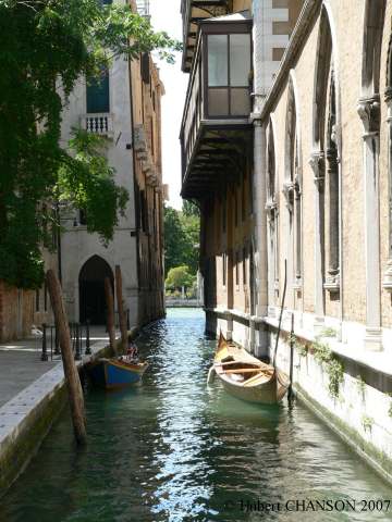
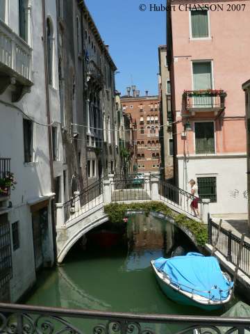
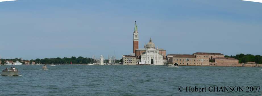
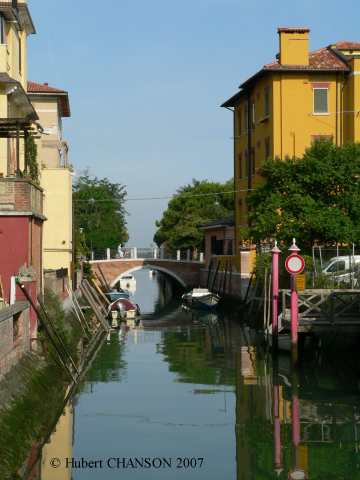
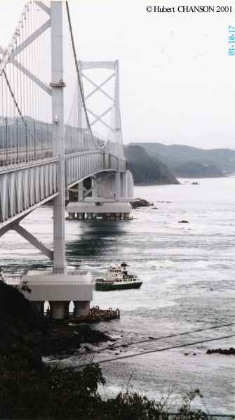
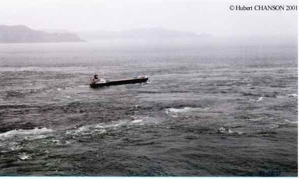
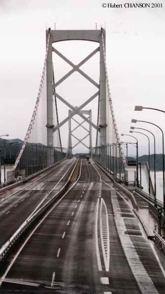
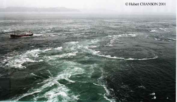
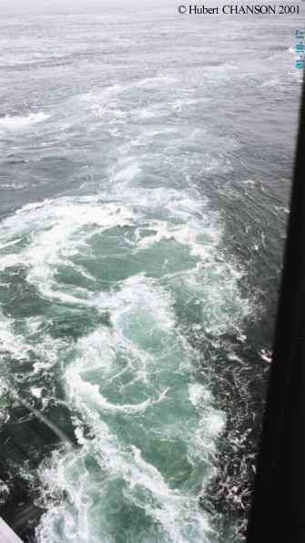
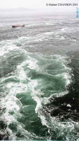
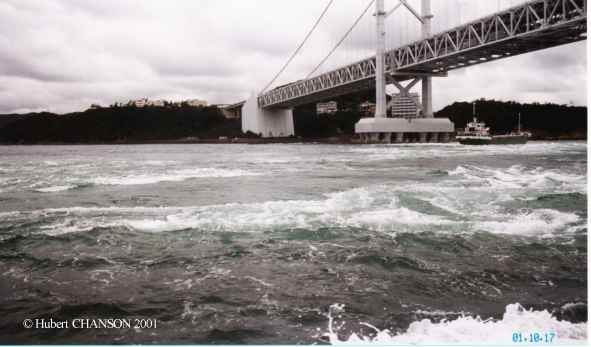
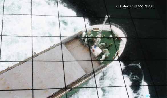
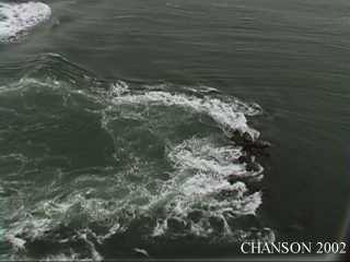
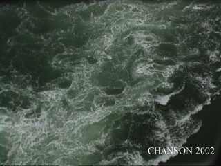
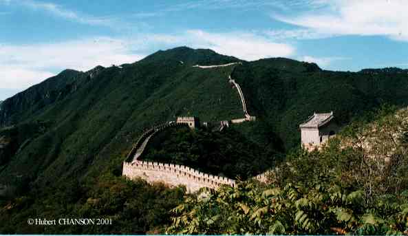
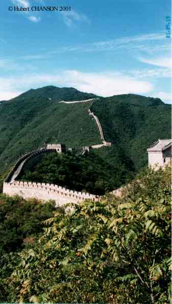
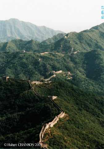
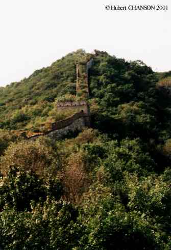
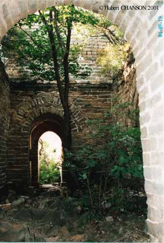
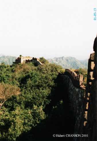
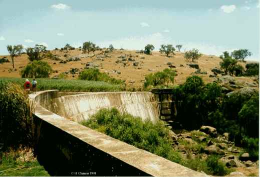
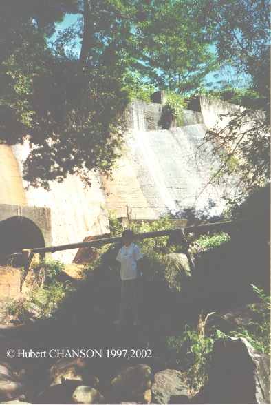
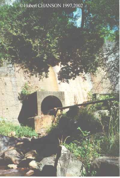
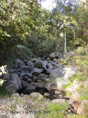
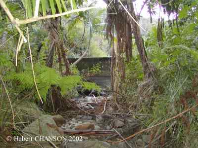
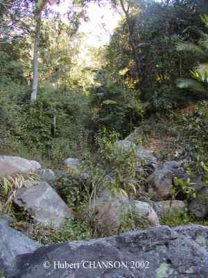
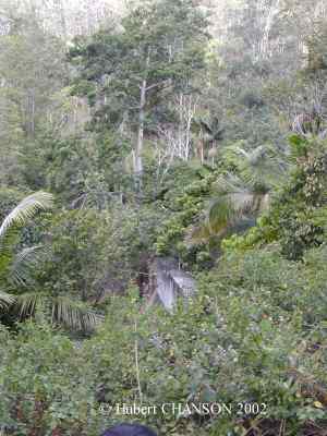
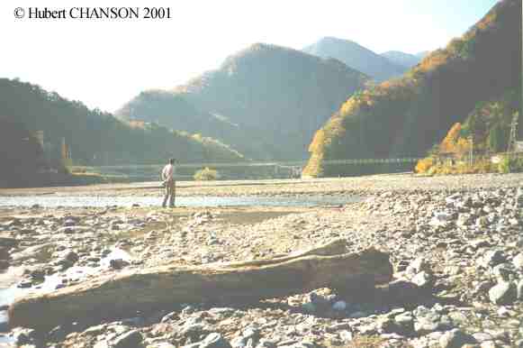
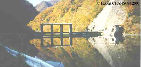
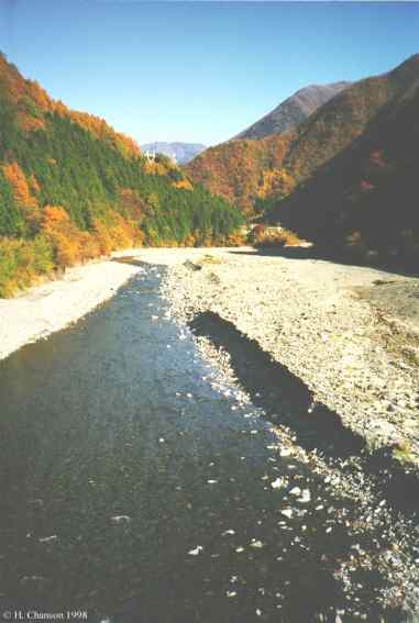
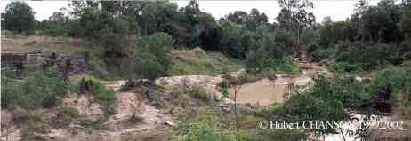
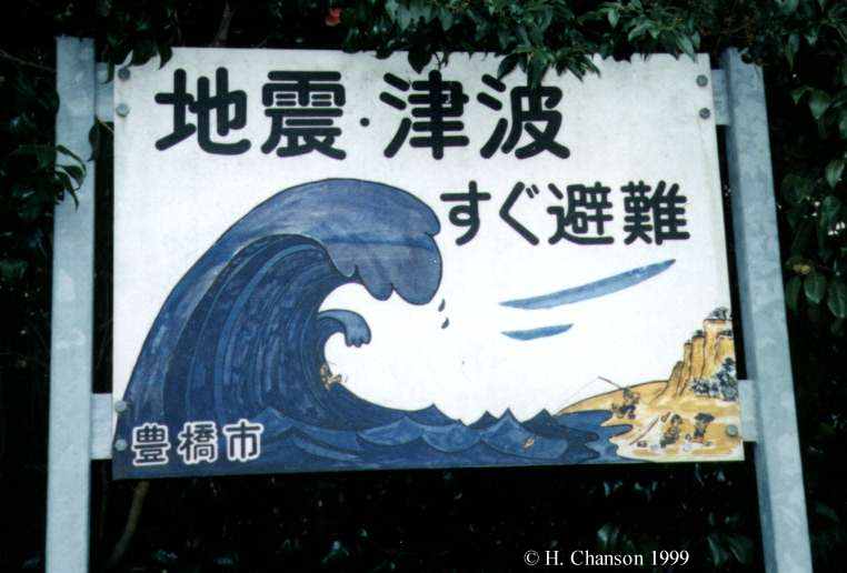
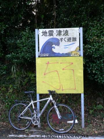
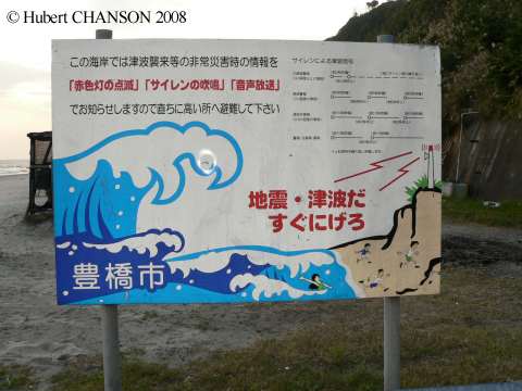
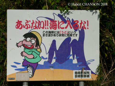
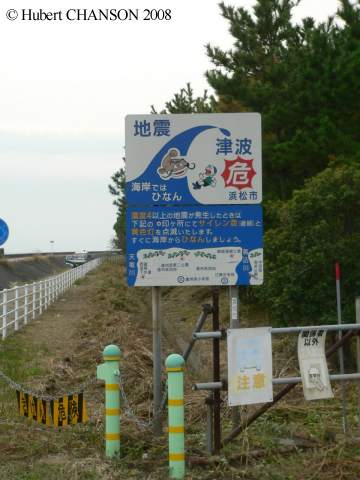
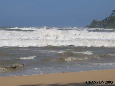
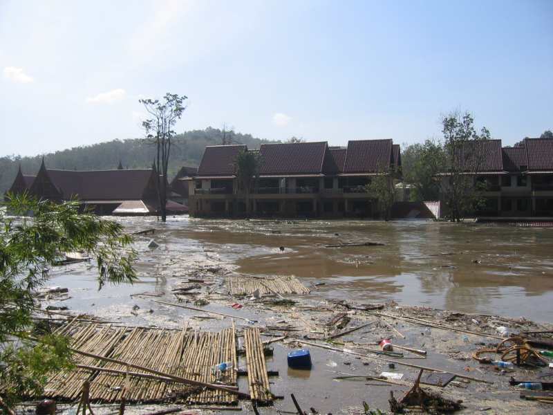
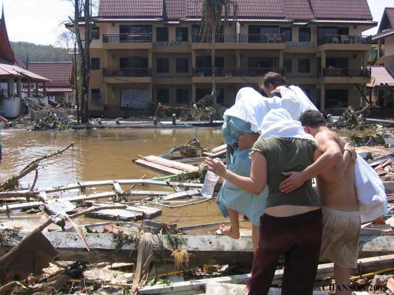
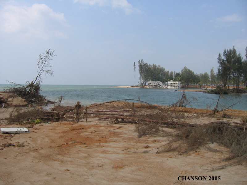
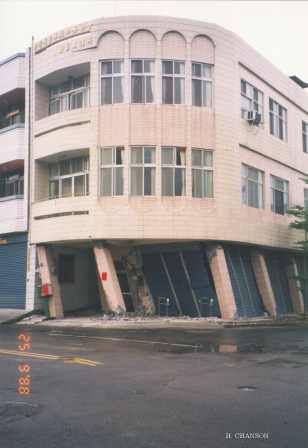
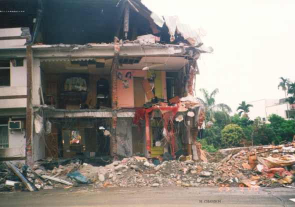
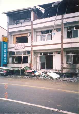
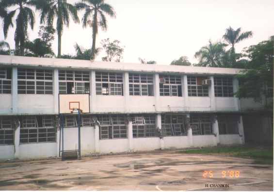
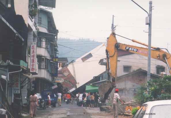
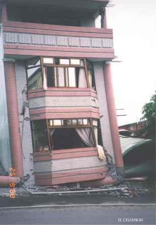
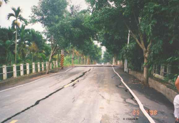
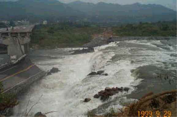
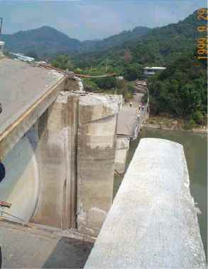
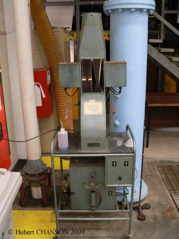
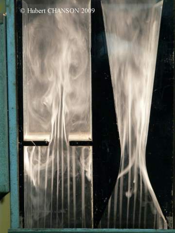
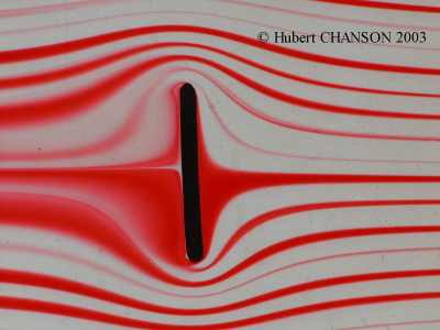
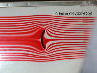
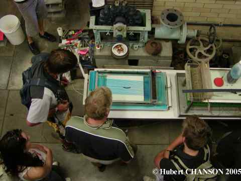
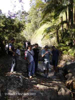
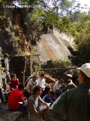
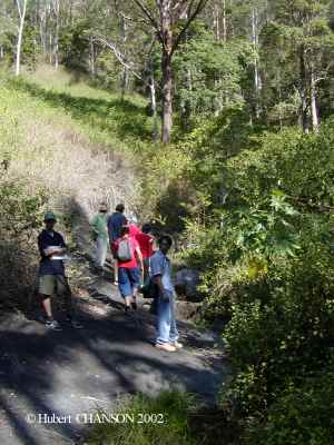
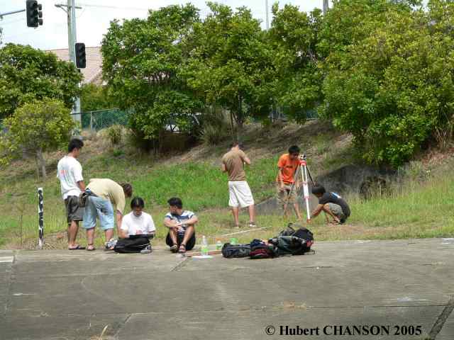